


Hydrastep 2468CB and 2468CD Manual 2468CB & 2468CD Dual Power Supply Version
24685034
2-1
2
2468CB & 2468CD
Dual Power Supply Version
Contents
Page No.
2.1 INTRODUCTION ....................................................................................... 2-3
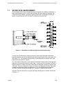
2.2 ELECTRODE CABLING SYSTEM ........................................................... 2-3
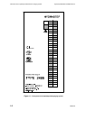
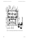
2.3 ELECTRONIC ENCLOSURE .................................................................... 2-3
2.3.1 INPUT BOARD (PCB 24680501 AND PCB 24680516) ......................... 2-5
2.3.1.1 Analogue Output Drive Capability ........................................... 2-5
2.3.2 REMOTE DISPLAY DRIVE CAPABILITY .............................................. 2-5
2.3.3 DISPLAY BOARD (PCB 24680515)....................................................... 2-6
2.3.3.1 Link LK1 .................................................................................. 2-6
2.3.3.2 Links LK2, LK3, LK4 and LK5 ................................................. 2-7
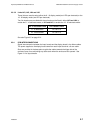
2.3.4 PCB INTERCONNECTIONS .................................................................. 2-7
2.4 INSTALLATION ........................................................................................ 2-8
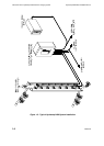
2.4.1 MECHANICAL INSTALLATION ............................................................. 2-8
2.4.2 ELECTRICAL INSTALLATION ............................................................. 2-10
2.4.2.1 Electrode Connections .......................................................... 2-10
2.4.2.2 Connecting Cables to Water Column Electrodes ................. 2-11
2.4.2.3 Connecting the Electrode Cable Assemblies to 2468
Enclosure………………………………………………………....2-12
2.4.2.4 Hydrastep Power Supply Cables .......................................... 2-13
2.4.2.5 Analogue Output Connection ................................................ 2-15
2.4.2.6 Opto-Isolated Fault Output Connection ................................ 2-16
2.5 SYSTEM CONFIGURATION .................................................................. 2-17
2.5.1 INPUT BOARD (PCB 24680501 OR 24680516) ................................. 2-17
2.5.1.1 Analogue Output Configuration ............................................. 2-17
2.5.1.2 Pulsed Output Setting ........................................................... 2-18
2.5.1.3 Electrode Error Configuration ............................................... 2-18
2.5.1.4 Configuring the Unit to Detect Electrode Error ..................... 2-19