


Hydrastep 2468CB and 2468CD Manual 2468CB & 2468CD Dual Power Supply Version
24685034 2-3
2.1 INTRODUCTION
This chapter introduces the dual power supply version of the Hydrastep 2468 Electronic
Gauging System, its mechanical installation, system configuration, simple fault
analysis/corrective action capability and its specification.
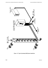
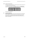
2.2 ELECTRODE CABLING SYSTEM
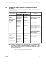
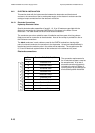
This system can have 8, 10, 12, 14, 16, 18, 20, 22, 24, 26, 28, 30 or 32 electrodes and uses
18-core electrode cables. The cables consist of nine pairs of coloured cores with the black
cores in each cable used for the EARTH terminations. Each electrode requires one pair of
cores, one core for the signal drive and one for the signal return.
Number of
Electrodes
Number of Cables
Required
8
10-16
18-24
26-32
1
2
3 or 4
4
The electrode cable is pre-formed for simple installation. The connections to the electrodes
are terminated on the connection stud of the electrode. Either core can be connected to the
electronic enclosure as the signal drive or return.
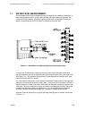
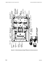
2.3 ELECTRONIC ENCLOSURE
The basic arrangement of boards in the electronic enclosure is as follows:
Two input boards supply power to the system and to the input signal processing
circuits. These boards are: PCB 24680501, ac (mains) input, or PCB 24680516, dc
input. One board is mounted on the right hand side of the base plate and receives the
odd numbered electrode inputs. The other board is mounted on the left hand side of
the base plate and receives the even numbered electrode inputs.
A display board (PCB 24680515) contains the LED drive circuits for the two columns
(32 red LEDs and 32 green LEDs) and the system fault LEDs. This board is mounted
on the rear of the front panel, with the LEDs protruding through the front panel.
Up to four output boards, Relay Board (PCB 24680504), Relay with time delay Board
(24680509) or Opto-isolator Board (PCB 24680505) may be fitted, two per input
board. Output board mounting pillars are fitted to each input board during
manufacture to support the first output board mounted.
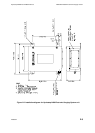
Refer to Figure 2.1 on page 2-4 for an annotated view of the internal layout of the unit.