


Hydrastep 2468CB and 2468CD Manual Relay Output Board Option
24685034 3a-3
3A.1 GENERAL DESCRIPTION
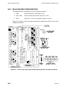
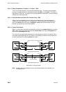
The Relay Output Board (PCB 24680504) has four relays and is mounted on top of the input
board using 3 nylon spacers. Electrical connection between the two boards is via plug and
socket (SK1 on the input board and PL1 on the relay output board).
A second relay output board may be mounted on top of the first on nylon spacers. Holes
have been drilled on all relay output boards to receive the 3 nylon spacers. The top board is
offset towards the centre of the unit improving the cable layout from the relay output boards.
The nylon spacer fixing holes and mounting holes are illustrated in Figure 3a.1 on page 3a-6.
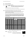
Each of the 4 relays can be energised by any one of up to 16 electrodes, with an individual
choice of being energised when its selected electrode is in steam or is in water.
Furthermore, relay RL1 can be used to monitor an electrode state or to register an ALARM
condition. When set to register the ALARM state, the relay is energised in the ‘system
normal’ state and de-energises when an ALARM condition exists.
This option comes complete with the nylon spacers and two 8-way output sockets.
3A.2 INSTALLATION
This sub-section deals with the mechanical and electrical installation of the Relay Output
Board (PCB 24680504) option. In the rest of this chapter the ‘relay output board’ title is
shortened to ‘relay board’.
3A.2.1 STORAGE & PRE-INSTALLATION INSPECTION
3a.2.1.1 Storage Area
The storage area must be dry, dust-free and kept at a reasonable temperature. The storage
area should allow for access and inspection of all items of equipment.
3a.2.1.2 Pre-Installation Inspection
Open the option package and inspect the contents for signs of damage. Check contents for
completeness.
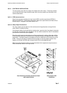
3A.2.2 MECHANICAL INSTALLATION
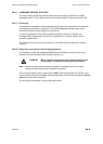
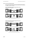
The output board is mounted directly on top of the input board. The input board is supplied
with three nylon spacers fitted. The output board is then aligned on its Berg socket/plug
interconnection (PL1/SK1) and input board-mounted spacers and pressed home on to the
spacers.
When two output boards are required to be mounted on an input board, the second output
board is mounted on three nylon spacers fitted on the first mounted output board.