


Hydrastep 2468CB and 2468CD Manual 2468CB & 2468CD Dual Power Supply Version
24685034 2-7
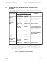
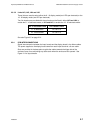
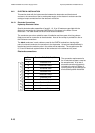
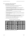
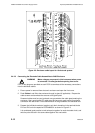
2.3.3.2 Links LK2, LK3, LK4 and LK5
These links are used to select either the 8 - 16 display mode (two LEDs per electrode) or the
18 - 32 display mode (one LED per electrode).
Two link headers are provided with the unit and must be fitted in either LK2 and LK4, to
enable the 8 - 16 electrode mode, or LK3 and LK5, to enable the 18 - 32 electrode mode.
No. of Electrodes used Link Headers fitted
8 - 16 electrodes LK 2 & LK 4
18 - 32 electrodes LK 3 & LK 5
See also Figure 2.5 on page 2-21.
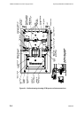
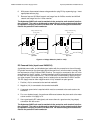
2.3.4 PCB INTERCONNECTIONS
Signal interconnection between the input boards and the display board is via ribbon cables.
The power supplies to the display board come from each input board via a 6-core cable.
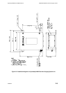
Slots are provided in the base plate to guide the cables towards the hinge-side of the
enclosure case, thus minimising any cable strain when the enclosure lid is opened. See
Figure 2.1 for layout details.