


2468CB & 2468CD Dual Power Supply Version Hydrastep 2468CB and 2468CD Manual
2-24 24685034
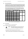
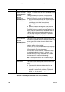
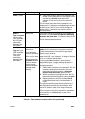
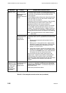
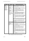
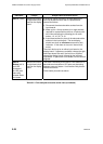
Indication Fault(s) Analysis and Corrective Action
State 1 (contd.)
Incorrect wiring,
broken connection
or damaged cable
assembly
Affected
electrode(s)
alternate between
water and steam.
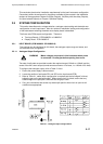
Check ac voltage on electrodes with a true r.m.s.
voltmeter. A voltage of less than 0.1V ac indicates a fault
condition.
If wiring to the electrode is correct and the electrode
gives a voltage reading of greater than 0.1V ac and a
fault is still indicated, carry out the following procedure:
1. Remove both conductors from the suspect electrode.
With the conductors isolated from each other, the
level display should show the electrode as
alternating between water and steam (green and
red).
2. With the conductors touching each other, the level
display should show electrode as being in steam.
The above procedure checks the electrode wiring. If the
display does not show the correct results, then check for
a break in either of the suspect electrode conductors.
Carry out repair to any faulty connection or substitute a
new conductor or cable assembly in place of the
defective item.
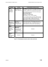
Dirt on electrode
Affected
electrode(s)
alternate between
water and steam.
If the wiring checks carried out as described above have
not located a fault, then dirt on an electrode insulator may
be the cause of the problem giving an effective short-
circuit to ground.
Check the electrodes for dirt over the external insulator
and clean with a cloth as required.
Checking for dirt on the internal insulator of the electrode
requires the draining of the water column (refer to Part 2
of this manual for the correct procedure).
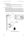
Once the water column is drained, check the ac voltage
on each electrode using a true r.m.s. voltmeter. Any
electrode showing a voltage of less than 3V ac needs
cleaning or replacement. Electrodes must be removed
from the column for inspection and cleaning.
Note: The electrode insulator can be cleaned using a
clean cloth
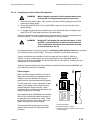
Internal fault If the wiring checks carried out as described above have
not located a fault, then it is possible an internal fault
exists.
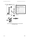
1. Disconnect the electrode cable sockets from the
input board.
2. Make up four 10-way sockets (six or eight sockets
required for systems with more than 16 points) with
wire links connecting the following pins on each
socket; 1-2, 4-5, 6-7, 9-10.
Table 2.3 - Fault analysis/corrective action chart (continued)