


2468CB & 2468CD Dual Power Supply Version Hydrastep 2468CB and 2468CD Manual
2-8 24685034
2.4 INSTALLATION
This section deals with the mechanical installation of the electronic enclosure and the
electrical connections required for the basic system. Any installation dealing with the options
available for use on this version of the system are covered in Chapters 3 & 4.
Notes:
1. The Electronic Enclosure cover should not be removed or opened until the equipment is
ready for physical installation to its fixing point. Under no circumstances should the
Electronic Enclosure be left open unless internal work is actually in progress.
2. When working on a bench with the enclosure open, the lid should be supported in its
open position.
3. To clean the instrument, use a damp cloth with a mild, water-based cleaner. Clean the
exterior of the instrument only. Do not allow liquids to enter or spill into the instrument.
2.4.1 MECHANICAL INSTALLATION
The electronic enclosure must be sited within electrode cable length of the water column fixture.
The preferred site for the electronic enclosure is a wall or vertical bracket structure where easy
access is available for viewing and servicing, and of suitable composition/load bearing ability to
be capable of supporting 4 times the equipment weight (see page 2-32 for weight specification.)
It is assumed that the water column is fully installed.
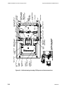
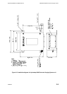
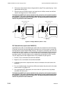
The electronic enclosure is equipped with four welded feet, allowing it to be secured in a
vertical position. Using a template derived from the enclosure details, given in Figure 2.2,
drill the necessary holes in the prepared surface. Secure the electronic enclosure with M10
bolts or equivalent fixings.
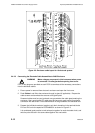
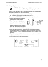
The wiring enters the unit through a gland plate in the bottom of the enclosure. A blank
gland plate is provided to give users a choice in the type of glands and gland configuration
for the required system. Alternatively, cable entry can be made directly via trunking. Note
that the gland plate should be removed for fitting of the glands. EMC compatibility for
European installations is proven for an enclosure using a gland plate and RF glands making
a good annular (ring shape) connection to screened cables for all connections. An
installation using unscreened cables or trunked routing without a gland plate and RF gland
would not be covered by the manufacturer’s EMC declaration of conformity.
The cabling involved is:
Mains Supplies (2 cables) Remote Display (up to 6 cables)
Electrode Inputs (up to 4 cables) Analogue Outputs (1 or 2 cables)
Relay or Opto-isolated Outputs Opto-isolated Fault Output (1 cable)
(Up to 16 relay or opto-isolated outputs)