


Relay Output Board Option Hydrastep 2468CB and 2468CD Manual
3a-8 24685034
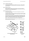
3a.3.1.3 Relay Energisation (‘In Steam’ or ‘In Water’) - SW5
This is a four-channel switch, one channel allocated per relay. The switch selects whether
the relay is energised when the selected electrode is in water or is in steam. This switch is
highlighted in Figure 3a.1 (on page 3a-6) to provide additional information on channel identity
and the switch ‘electrode state’.
3a.3.1.4 Electrode/Alarm Operation (RL1 Function Only) - SW6
Relay 1 can be configured to receive either an electrode input or it can be used as the
‘system fault’ relay (see Figure 3a.1 on page 3a-6). When configured as the system fault
relay, the normal state of the relay is energised, a fault state will de-energise the relay.
See the next section for contact output details.
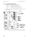
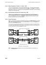
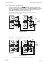
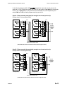
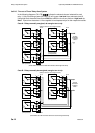
3a.3.1.5 System Fault Output
Relay 1 on each relay board can be configured to be used as a system fault relay by setting
SW6. When used as a system fault relay the normal state of the relay is energised and a
fault state will de-energise the relay.
The relay will only output faults detected by the input board onto which it is installed. With a
dual power supply Hydrastep unit, this means it is necessary to used two relay boards (one
on each input board) to create a system fault output.
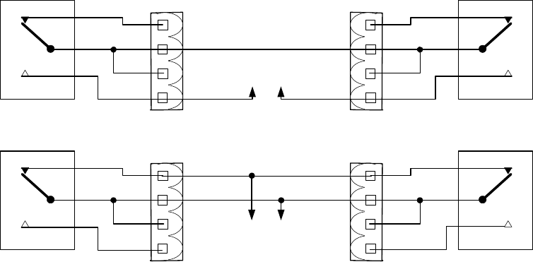
(Relays shown in de-energised state)
(Switch SW6 set for fault signal operation)
Alarm off when contacts closed
Even fault relay
(LH input board)
RL 1
1
4
3
2
To alarm annunciator
RL 1
1
4
3
2
PL 2 PL 2
Odd fault relay
(RH input board)
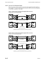
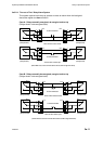
Alarm off when contacts open
Even fault relay
(LH input board)
RL 1
1
4
3
2
To alarm annunciator
RL 1
1
4
3
2
PL 2 PL 2
Odd fault relay
(RH input board)
Note: Systems with a local display have an opto-isolated system fault available from
the display board.