


Hydrastep 2468CB and 2468CD Manual Introduction to the Hydrastep 2468 Electronic Gauging System
24685034
1-5
1.2 HYDRASTEP 2468 ELECTRONIC GAUGING SYSTEM
The Hydrastep 2468 is a sophisticated and flexible electronic gauging system. It is supplied
in two main versions:
A Single Power Supply System with Local Level Display
A Dual Power Supply System with Local Level Display
For both systems, the printed circuit boards are housed in the same enclosure, allowing
customers full capability to expand their system as and when conditions dictate.
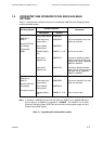
Table 1.1 on page 1.7 is a summary of all upgrade paths and options for the Hydrastep 2468
system.
1.2.1 INPUT BOARDS
All versions of the Hydrastep 2468 unit contain one or two input boards. The input boards
mount on to the base plate in the enclosure. Each input board provides power supplies,
electrode drive, signal processing, fault analysis and an analogue output.
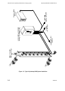
The input board can accept inputs from 8, 10, 12, 14 or 16 electrodes. When two input
boards are used (in a ‘dual power supply’ system) the electrodes are ‘interlaced’; that is, the
odd numbered electrodes are connected to one input board and the even numbered
electrodes are connected to the other. Full details of the wiring are covered in Chapter 2
under Installation.
Each input board also includes a current output circuit that provides an analogue
representation of the water level in the column. The analogue output can be configured to
give a current output in one of the following ranges:
0 to 20mA
4 to 20mA
20 to 0mA
20 to 4mA
1.2.2 DISPLAY BOARD
The display board is mounted on to the hinged lid of the unit and provides indication through
the viewing window on the enclosure. It also supplies configuration information to the input
board(s); that is, the number of electrodes connected to the unit and the required
water/steam switching threshold.
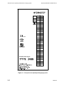
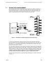
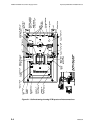
Figure 1.1 shows the local display with water level and system fault indication. Water level
is indicated by two columns of LEDs, one red to indicate steam and one green to indicate
water. The number of LEDs illuminated is dependent on the number of electrodes present
and a blanking panel is available to mask the LEDs not used. In addition to the system fault
indication is an opto-isolated system fault output. Switches are provided to allow the
number of electrodes to be selected (8, 10, 12, 14, 16, 18, 20, 22, 24, 26, 28, 30 or 32). Two
solder link pads are provided to select the water/steam switching threshold (0.6S/cm or
1.6S/cm).