


Hydrastep 2468CB & 2468CD Manual Remote Display Options 24683B, C & D
24685034 4-3
4.1 REMOTE DISPLAY OPTIONS
The 24683B, C, and D Remote Display Units give a repeat display of the water level state
and fault alarm state of the Hydrastep 2468 Electronic Gauging System.
Each type of remote display operates in the same way. The only difference between them is
in their mechanical construction. The 24683B is a small LED display for panel mounting; the
24683C is a large LED display for panel mounting; and the 24683D is a large LED display for
wall mounting, contained in a splash proof box to IP65 (NEMA 4X) standard.
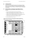
On each type of remote display there are two columns of LEDs, a red column to indicate
steam and a green column to indicate water. This provides a clear indication of the water
level in the monitored system. The number of LEDs that may be illuminated depends on the
number of electrodes being used. To mask the unused LEDs, a blanking panel is provided:
this should be fitted on the inside of the front panel. An electrode fault, or a wiring or circuit
fault, is indicated by a yellow LED.
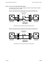
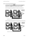
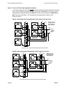
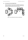
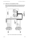
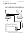
The 2468 will drive a maximum of six remote displays, using star or daisy chain connections.
One remote display can be powered from the 2468. All other remote displays must be
locally powered.
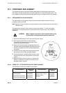
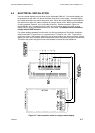
On each type of remote display, connection to the 2468 is made through a 20-way screw
clamp terminal block. Access to the terminal block on the 24683B and 24683C is via a cut-
out in the rear panel. Access to the terminal block on the 24683D is made via cable glands
on one end of the enclosure.