


Hydrastep 2468CB & 2468CD Manual Opto-isolated Output Board Option
24685034 3c-1
3c
2468 Opto-isolated Output Board Option
Contents
Page No.
3C.1 GENERAL DESCRIPTION ........................................................................................ 3
3C.2 INSTALLATION ......................................................................................................... 3
3C.2.1 STORAGE & PRE-INSTALLATION INSPECTION ................................... 3
3c.2.1.1 Storage Area ............................................................................... 3
3c.2.1.2 Pre-installation Inspection ........................................................... 3
3C.2.2 MECHANICAL INSTALLATION ................................................................ 4
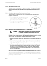
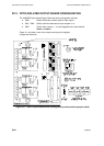
3c.2.2.1 Fitting Nylon Spacers to the Opto-Isolated Output Board .......... 4
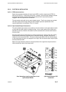
3c.2.2.2 Mounting the Opto-Isolated Output Board on to the Input Board 4
3C.2.3 ELECTRICAL INSTALLATION ................................................................. 5
3c.2.3.1 PCB Interconnections ................................................................. 5
3c.2.3.2 Opto-Isolated Output Connections.............................................. 5
3C.3 OPTO-ISOLATED OUTPUT BOARD CONFIGURATION........................................ 6
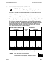
3C.3.1 CONFIGURING THE OPTO-ISOLATED OUTPUT BOARD ..................... 7
3c.3.1.1 Electrode/Opto-Output Selection (Opto-1, Opto-2, Opto-3 &
Opto-4 Outputs) - SW1 to SW4 .................................................. 7
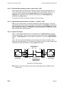
3c.3.1.2 Electrode/Alarm Operation (output 1 function only) - SW6 ......... 8
3c.3.1.3 Opto-Isolated Output Activation (‘In Steam’ or ‘In Water’) -
SW5 ............................................................................................ 8
3c.3.1.4 System Fault Output ................................................................... 8
3C.3.2 ALARM AND TRIPPING FACILITIES ....................................................... 9
3c.3.2.1 Philosophy ................................................................................... 9
3c.3.2.2 Opto-Output Interconnections for Alarm/Tripping Systems ........ 9
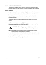
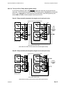
3c.3.2.3 ‘One out of Two’ Opto-output Alarm System ............................ 10
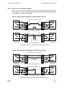
3c.3.2.4 ‘Two out of Two’ Opto-output Alarm System ............................ 11
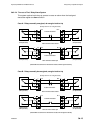
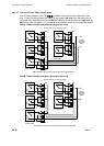
3c.3.2.5 ‘Two out of Four’ Opto-output Alarm System ............................ 12
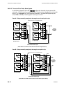
3c.3.2.6 ‘Two out of Three’ Opto-output Alarm System .......................... 13
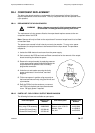
3C.4 COMPONENT REPLACEMENT ............................................................................. 14
3C.4.1 REPLACEMENT OF NYLON SPACERS ................................................ 14
3C.4.2 PARTS LIST - OPTO-ISOLATED OUTPUT BOARD 24680505 ............ 14
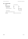
3C.5 SPECIFICATION ..................................................................................................... 15