


2468CB & 2468CD Dual Power Supply Version Hydrastep 2468CB and 2468CD Manual
2-30 24685034
2.6.1 COMPONENT REPLACEMENT
The Hydrastep 2468 contains no user-replaceable components. Board failure requires the
replacement of the entire printed circuit board.
WARNING Mains voltages are present in this instrument when power
is connected. De-energise before opening front cover.
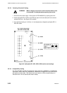
2.6.1.1 Removing the Input Board (24680501 or 24680516)
The input board is secured on to the base plate of the electronic enclosure by seven set
screws and washers, distributed one at each corner of the board and three in the board
centre. See Figure 2.1. To remove the input board, carry out the following procedure:
1. Isolate the electronic enclosure from the ac (mains) or dc supply and open the lid.
2. Unplug the supply connector TB1.
3. Unplug the electrode input connectors PL2, 3, 4 and 5 as necessary and the analogue
output connector PL1 (if used) from the input board.
4. Disconnect the ribbon cable connector on the display board and the display board power
cable socket on the input board - see Figure 2.1 on page 2-4.
5. Undo the seven securing screws and remove them and their washers. Lift off the input
board from the base plate.
2.6.1.2 Refitting the Input Board
To refit the input board, carry out the removal procedure in the reverse order.
2.6.1.3 Removing the Display Board 24680515
The display board is attached to pillars mounted on the rear of the front panel by five
securing nuts and washers. See Figure 2.1 on page 2-4.
To remove the display board, carry out the following procedure:
1. Isolate the electronic enclosure from the mains supply and open the lid.
2. Disconnect the ribbon cable socket and the display board power cable socket from the
display board, see Figure 2.1. Remove remote display and system fault connections if
applicable.
3. Undo the five securing nuts and remove them and their washers. Lift off the display
board from the attachment pillars.
2.6.1.4 Refitting the Display Board
To refit the display board, carry out the removal procedure in the reverse order.
Note: Special attention must be taken to ensure the lid screening is satisfactory after any
display board refitting. The screening cable is taken to the bottom left hand securing
screw on the display plate and this connection must have good conductivity.