


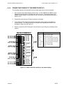


Hydrastep 2468CB & 2468CD Manual Remote Display Options 24683B, C & D
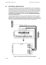
24685034 4-15
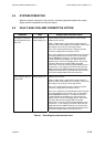
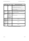
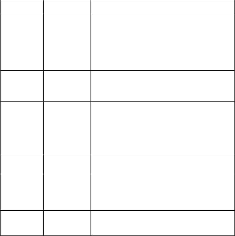
Indication Fault Analysis and Corrective Action
Flickering Display Corruption of signal
data
Most probably caused by bad shielding (screening) of the remote
display cabling or by bad shield connections to ground.
Check shielding and shield connections. Ensure that only one
end of the cable shield is connected to ground.
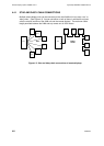
If several remote displays are ‘daisy chained’ together then a
termination resistor may be required on the end display. (See
Section 4.4.3 in this chapter.)
Chequered
pattern on red
and green LED
display
Wrong setting of
‘Number of
Electrodes’ switch
on 2468 display
board.
Refer to Section 2.3 in Chapter 2 and ensure that the switch is set
correctly. If the display still shows a chequered pattern then a
circuit fault exists on the 2468 display board. Remove this board
and fit a serviceable replacement.
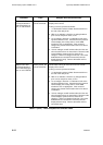
On/off pattern on
red and green
LEDs.
Wrong setting of
‘Number of
Electrodes’ switch
on 2468 display
board, or wrong
setting of links LK1,
LK2, LK3 and LK4
on the 24683BB
decoding pcb.
As above.
If a fault is not found, check the link setting on the 24683BB and
reset the links if necessary.
Indication not
displayed for
lower electrodes.
As above.
As above.
Each electrode
represented by
only one LED
when 16 or less
electrodes are
used.
As above.
As above.
LEDs display an
irregular
red/green
pattern.
As above.
As above.
Table 4.1 (cont.) - Fault Analysis and Correction Chart