


Hydrastep 2468CB & 2468CD Manual Remote Display Options 24683B, C & D
24685034 4-13
4.5 SYSTEM OPERATION
When the system is brought on line check for complete agreement between the remote
display and the Hydrastep level indicator display.
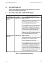
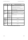
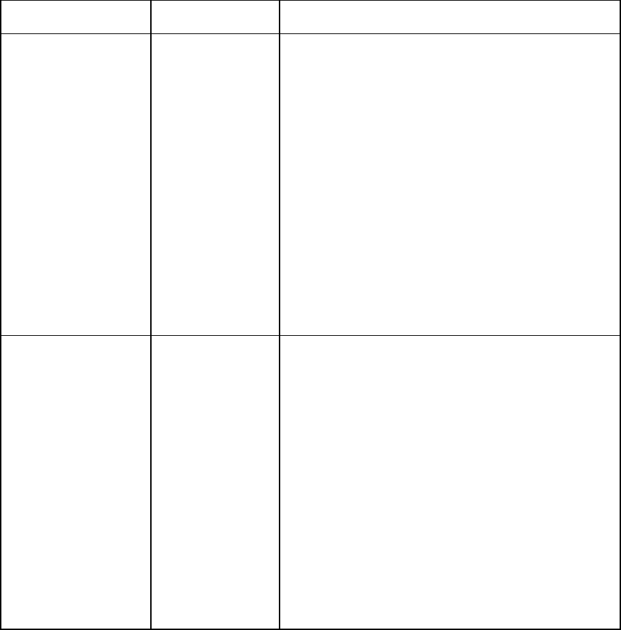
4.6 FAULT ANALYSIS AND CORRECTIVE ACTION
Indication Fault Analysis and Corrective Action
No display of odd LEDs
(including bottom half of
fault LED.
Loss of power to
remote display unit.
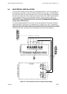
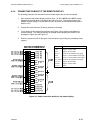
Check that the wiring to connector PL1 in the remote
display unit is correct.
With a suitable meter, check that the supply voltage is
present at the remote display unit connector. Ensure that
the voltage is in the range 14V through 45Vdc.
If the unit is locally powered and no voltage is present
check the voltage at the local power source.
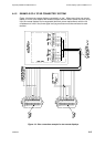
If the unit is powered from the 2468 electronics unit check
the voltage between pins 5 and 8 of PL3 on the display
board (24680502) of that unit. A voltage of less than
14Vdc indicates the possibility of a short circuit in the
power lines or a fault on the display board. Disconnect
connector SK3 from the display PCB in the 2468
electronics unit and re-check the voltage between pins 5
and 8 of PL3. If the voltage is less than 18Vdc then the
display board in the 2468 electronics unit may be faulty.
Replace this board with a serviceable item and check for
the correct voltage between pins 5 and 8 of PL3.
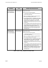
No display of even
LEDs (including top half
of fault LED).
Loss of power to
remote display unit.
Check that the wiring to connector PL2 in the remote
display unit is correct.
With a suitable meter, check that the supply voltage is
present at the remote display unit connector. Ensure that
the voltage is in the range 14V through 45Vdc.
If the unit is locally powered and no voltage is present
check the voltage at the local power source.
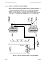
If the unit is powered from the 2468 electronics unit check
the voltage between pins 5 and 8 of PL7 on the display
board (24680502) of that unit. A voltage of less than
14Vdc indicates the possibility of a short circuit in the
power lines or a fault on the display board. Disconnect
connector SK3 from the display PCB in the 2468
electronics unit and re-check the voltage between pins 5
and 8 of PL7. If the voltage is less than 18Vdc then the
display board in the 2468 electronics unit may be faulty.
Replace this board with a serviceable item and check for
the correct voltage between pins 5 and 8 of PL7.
Table 4.1 - Fault Analysis and Correction Chart