


Hydrastep 2468CB and 2468CD Manual 2468CB & 2468CD Dual Power Supply Version
24685034 2-17
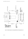
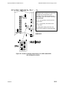
This concludes the electrical installation requirements for the basic instrument configuration.
Connections within the enclosure for the options available will be covered in the Installation
sections of the appropriate Chapter 3a (Relay Outputs), 3b (Relay with time delay Outputs),
3c (Opto-isolated Outputs) or Chapter 4 (Remote Display).
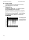
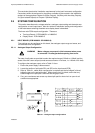
2.5 SYSTEM CONFIGURATION
This section describes mains voltage selection, analogue output setting and electrode error
configuration on each input board. Also the ‘number of electrodes’ setting and configuration
of the water/steam switching threshold value display board is described.
The three main PCBs require configuration. These are:
Two Input Boards - PCB 24680501 or 24680516
Display Board - PCB 24680515
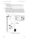
2.5.1 INPUT BOARD (PCB 24680501 OR 24680516)
Two settings may be configured on this board, the analogue output range and sense, and
the electrode error configuration.
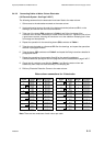
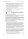
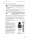
2.5.1.1 Analogue Output Configuration
WARNING Mains voltages are present in this instrument when power
is connected. De-energise before opening front cover.
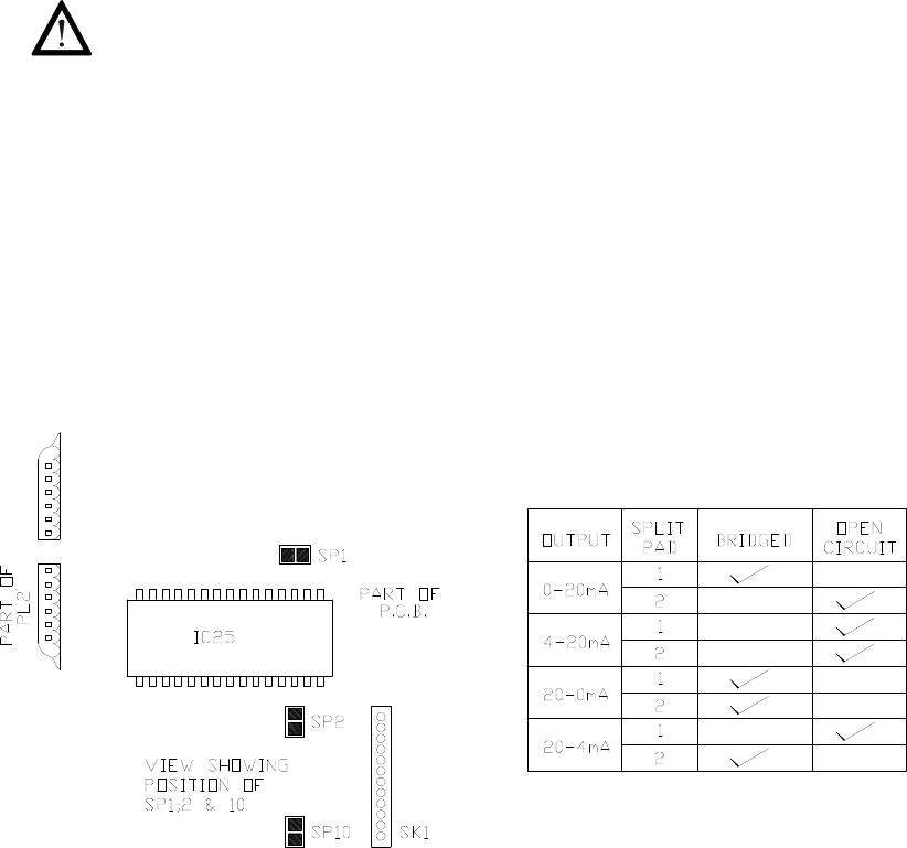
Two sets of split pads are provided to select the required range (0-20mA or 4-20mA) and the
sense of the mA current output (normal sense as shown or in reverse, i.e. 4-20mA or 20-4mA).
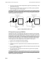
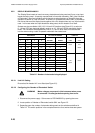
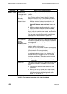
To configure the analogue output, refer to Table 2.1 then:
1. Ensure the power supply is disconnected.
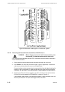
2. Locate the position of split pads SP1 and SP2 on the input board (PCB).
3. Refer to Table 2.1, select which configuration is required and where ‘bridged’ is ticked,
bridge the gap on the pad with solder. Where ‘open circuit’ is ticked, ensure that any
solder bridge on the split pad is removed and the gap is clean.
4. Carry out a resistance test across any altered split pad for short circuit or open circuit
conditions as appropriate.
Table 2.1 - Analogue output configurations