


Hydrastep 2468CB and 2468CD Manual Delay Relay Output Board Option
24685034
3b-1
3b
Delay Relay Output Board Option
Contents
Page No.
3B.1 GENERAL DESCRIPTION ........................................................................................ 3
3B.2 INSTALLATION ......................................................................................................... 3
3B.2.1 STORAGE & PRE-INSTALLATION INSPECTION ................................... 3
3b.2.1.1 Storage Area ............................................................................... 3
3b.2.1.2 Pre-Installation Inspection ........................................................... 3
3B.2.2 MECHANICAL INSTALLATION ................................................................ 4
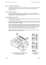
3b.2.2.1 Fitting the Nylon Spacers to the Delay Relay Output Board ....... 4
3b.2.2.2 Mounting the Delay Relay Output Board on to the Input Board . 4
3B.2.3 ELECTRICAL INSTALLATION ................................................................. 5
3b.2.3.1 PCB Interconnections ................................................................. 5
3b.2.3.2 Relay Output Connections .......................................................... 5
3B.3 DELAY RELAY BOARD CONFIGURATION ............................................................ 6
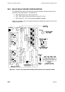
3B.3.1 DELAY RELAY OUTPUT BOARD ............................................................ 7
3b.3.1.1 Configuring the Delay Relay Output Board ................................. 7
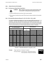
3b.3.1.2 Electrode/Relay Selection (Relays RL1, RL2, RL3 & RL4) - SW1
to SW4 ........................................................................................ 7
3b.3.1.3 Relay Energisation (‘In Steam’ or ‘In Water’) - SW5 ................... 8
3b.3.1.4 Electrode/Alarm Operation (RL1 function only) - SW6 ............... 8
3b.3.1.5 System Fault Output ................................................................... 8
3b.3.1.6 Delay Circuit Configuration ......................................................... 9
3b.3.1.7 Configuring the Delay Circuit Split Pads ................................... 10
3B.3.2 ALARM AND TRIPPING FACILITIES ..................................................... 11
3b.3.2.1 Philosophy ................................................................................. 11
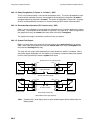
3b.3.2.2 Relay Interconnections for Alarm/Tripping Systems ................. 11
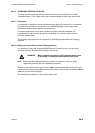
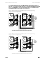
3b.3.2.3 ‘One out of Two’ Relay Alarm System ...................................... 12
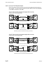
3b.3.2.4 ‘Two out of Two’ Relay Alarm System ...................................... 13
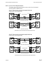
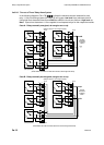
3b.3.2.5 ‘Two out of Four’ Relay Alarm System ..................................... 14
3b.3.2.6 ‘Two out of Four’ Relay Alarm System (contd.) ........................ 15
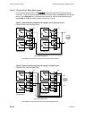
3b.3.2.7 ‘Two out of Three’ Relay Alarm System ................................... 16
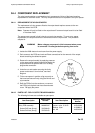
3B.4 COMPONENT REPLACEMENT ............................................................................. 17
3B.4.1 REPLACEMENT OF NYLON SPACERS ................................................ 17
3B.4.2 PARTS LIST - DELAY RELAY OUTPUT BOARD 24680509 ................ 17