


Opto-isolated Output Board Option Hydrastep 2468CB & 2468CD Manual
3c-12 24685034
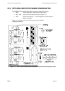
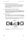
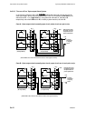
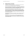
3c.3.2.5 ‘Two out of Four’ Opto-output Alarm System
In the following diagrams (5A & 5B)
indicate the electrode channel selected for
each opto-output. A fully functioning system (NO FAULTS) will perform a low level trip at
electrode level 3. For a high level trip, using electrode channels 11, 12, 9 and 10
respectively and switch SW5 set for W, a healthy system would trip at level 10.
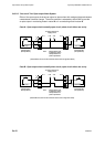
Case A - Opto-output circuit normally open circuit, short circuit one pair to trip
1
4
3
2
5
8
7
6
TR2
PL 2
(Switch SW5 is set to S for low level alarms and set to W for high level alarms)
Opto-output 1
TR4
Opto-output 2
+ VE
- VE
To alarm
annunciator
or tripping
device
1
4
3
2
5
8
7
6
TR2
Opto-output 1
TR4
Opto-output 2
PL 2
Note: External power must
be applied as shown.
See specification for
power requirements
Odd Electrodes
(RH Input Board)
Even Electrodes
(LH Input Board)
4
3
1
2
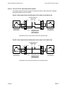
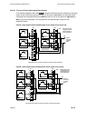
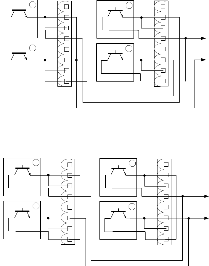
Case B - Opto-output circuit normally short circuit, open circuit one in each pair to trip
1
4
3
2
5
8
7
6
TR2
PL 2
(Switch SW5 is set to W for low level alarms and set to S for high level alarms)
Opto-output 1
TR4
Opto-output 2
+ VE
- VE
To alarm
annunciator
or tripping
device
1
4
3
2
5
8
7
6
TR2
Opto-output 1
TR4
Opto-output 2
PL 2
Note: External power must
be applied as shown.
See specification for
power requirements
Odd Electrodes
(RH Input Board)
Even Electrodes
(LH Input Board)
4
3
1
2