


Hydrastep Pressure Parts General Introduction
24675030
1-3
1.1 PRINCIPLE OF OPERATION
The Hydrastep systems have been designed as electronic alternatives to conventional visual
water gauges on boilers, giving more reliable and safer water level indication.
The system is based on the significant differences in resistivities of water and steam over
the range 100C (212F) to 370C (698F). (Series 3 super-critical components are used up
to 560C, 1040F)
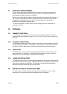
A vertical row of electrodes is installed in the water column which forms a side arm attached
to a boiler arid aligned, typically, such that an equal number of electrodes appear above and
below the normal water level, see Figure 1.1. The resistance measurement is made
between the insulated tip of the electrode and the wall of the column. The cell constant,
defining the actual resistance measured, is determined by the length and the diameter of the
electrode tip and the water column bore. In practice, the cell constant is chosen so that the
resistance in water is less than 100k ohms, with a consequent resistance in steam of greater
than 10M ohms.
Since the resistivities of water and steam are substantially different, the system is simple
and requires minimum setting up adjustments. It is not critical in terms of power supply
variations, ambient temperature changes, etc., resulting in a highly reliable system.
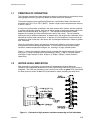
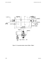
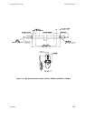
Figure 1.1 shows the resistance-measuring cell complete with installed electrode. Figure 1.2
and Figure 1.3 show examples of the Low Pressure (120bar, 1740p.s.i.) and the Series 3
and Super 3 High Pressure (210bar, 3045p.s.i. & 300bar, 4350p.s.i.) Water Columns
respectively.
1.2 WATER LEVEL INDICATION
Each electrode is connected to its own electronic measurement channel where the
resistance value measured decides which of two Light Emitting Diode (LED) drive circuits is
energised. The LEDs are presented in two columns, one column of green LEDs (illuminated
for water) and one column of red LEDs (illuminated for steam) indicating the water level.
Figure 1.1 - Schematic of high pressure resistance measuring cell and electrodes