


Hydrastep 2468CB & 2468CD Manual Opto-isolated Output Board Option
24685034
3c-5
3C.2.3 ELECTRICAL INSTALLATION
3c.2.3.1 PCB Interconnections
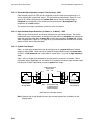
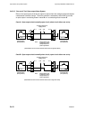
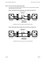
Signal interconnection between the input board (PCB 1) and the output board (PCB 5) is
direct via the SK1/PL1 12-way Berg connectors. Similarly, interconnection between the dual-
mounted output boards uses the same type connectors but the top board’s plug PL1
engages in the first output board’s socket SK1.
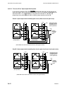
This sub-section deals with the four opto-isolated outputs. Two 8-way sockets are provided
with each output board through which the opto-isolated outputs are presented to their
external destinations via transistors TRs 2, 4, 6 and 8.
3c.2.3.2 Opto-Isolated Output Connections
The opto-isolated output states can be taken out of the enclosure via the gland plate (if used)
or along with the other cables in suitable trunking. One or more cables can be used at the
discretion of the user, however the cables must be screened and the screens terminated at
the gland plate.
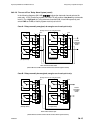
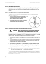
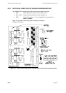
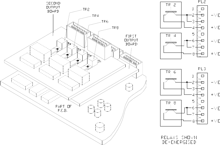
Since the output board is mounted on top of the input board, the routing of the relay cabling
should take the same kind of formation as the electrode cabling, arranged such that the
cables do not lie across the PCBs. The layout and plug pin details of the two affected plugs
on the output board is given in the diagram on the right, with the required opto-coupler output
terminal polarities shown.
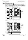
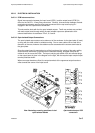
When two output boards are fitted, the output terminals of the uppermost output board are
offset towards the centre of the input board.
View illustrating mounting positions of dual
opto-isolated boards
Opto-isolated output PCB
connectors