


2468CB & 2468CD Dual Power Supply Version Hydrastep 2468CB and 2468CD Manual
2-6 24685034
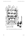
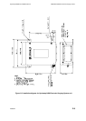
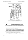
2.3.3 DISPLAY BOARD (PCB 24680515)
The display board receives its power supplies and electrode data from the input boards.
This data is decoded and used to illuminate the required LEDs mounted on the display
board. The data is also converted to serial format for transmission to remote display units.
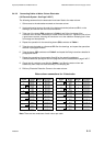
The water level in the column is indicated on the front panel by two columns of 32 LEDs, one
green column to indicate the electrodes which are in water and one red column to indicate
the electrodes which are in steam. The number of LEDs illuminated is dependent on the
number of electrodes being used in the system. When 8 to 16 electrodes are being used,
the unit illuminates two LEDs per electrode. When between 18 and 32 electrodes are being
used, the unit illuminates one LED per electrode. In both cases, the display is top biased
(unused LEDs are at the bottom of the display). A blanking label is provided to mask any
LEDs that are not used.
The system fault is indicated by the yellow LED. Provision is also made for external
indication of a system fault. This takes the form of an opto-isolated output which is normally
in its short-circuit state. When an alarm condition exists, the opto-isolated output is open-
circuited.
Full illumination of the Fault LED indicates a water above steam condition has been
detected. Illumination of half the Fault LED indicates an electrode, wiring or input board
related fault. The top half of the Fault LED illuminates when faults are detected by the left
hand input board (the even electrodes) and the bottom half of the Fault LED illuminates
when faults are detected by the right hand input board (the odd electrodes). Faults are
covered under “Fault Analysis & Corrective Action” in section 2.4 of this chapter.
The switch that sets the number of electrodes to be scanned is also mounted on this board.
A ‘chequered pattern’ is displayed by the RED and GREEN columns if an invalid switch
setting is made on the number of electrodes switch.
The water/steam switching threshold (0.6S/cm or 1.6S/cm) may be changed by solder
split pads.
2.3.3.1 Link LK1
The display board caters for both single input board and dual input boards versions of the
Hydrastep 2468 system. With dual input boards, the odd electrode inputs are connected to
one half of the display board circuit with the even electrode inputs connected to the other half
of the circuit.
With the single input board, only one half of the board is connected to the odd and even
electrode inputs. In this case the link LK1 must be fitted to connect the odd and even
halves of the display board circuit.
Note: This link MUST be removed for the dual input board system.