


Remote Display Options 24683B, C & D Hydrastep 2468CB & 2468CD Manual
4-6 24685034
4.3 MECHANICAL INSTALLATION
Of the three types of remote display units, types 24683B and 24683C are intended for panel
mounting and type 24683D is intended for wall mounting. The installation procedures for
panel and wall mounting are described below.
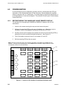
4.3.1 INSTALLING THE 24683B AND 24683C PANEL MOUNTED UNITS
The panel related dimensions for the 24683B and 24683C are:
Panel thickness: 24683B = 2mm to 9mm
24683C = 2mm to 20mm
Aperture: 24683B = 139mm high × 67mm wide
24683C = 186mm high × 92mm wide
The installation procedure is:
1. Ensure that the panel on which the remote display is to be fitted provides easy access
to the electrical connections and is sited in a good viewing position.
2. Cut an aperture in the panel to the dimensions given above and remove any burrs.
3. Remove the clamps (if fitted) from the remote display unit and fit the unit into the
aperture from the front of the panel.
4. Refit the clamps to the display unit and secure the unit to the panel.
The two clamps on the 24683B and 24683C each clip onto two metal studs on the case of
the unit. Adjust the clamps from the rear of the unit with a suitable flat bladed screwdriver.
Tighten the clamps until they press firmly against the panel to hold the unit in place.
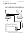
4.3.2 INSTALLING THE 24683D WALL MOUNTED UNIT
The 24683D Remote Display Unit is contained in an IP65 enclosure that can be fixed to the wall
by four mounting brackets. Cables are routed to the internal PCB through glands in the base.
The installation procedure is:
1. Place the unit against the surface to which it is to be fixed and mark the positions of the
fixing points. These should be positioned on centres 190mm apart horizontally and
305mm apart vertically. Install suitable fixings and secure the unit to the wall.
2. Remove the four screws securing the clear cover of the unit and place the cover
carefully to one side.
3. Remove the four screws securing the front panel of the unit and lay the panel, still
attached by its ribbon cable, on top of the case.
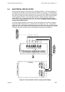
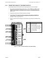
4. Loosen the cable gland nuts, pass the cables through the glands, prepare the cable
terminations, and fit the cable to the terminal block. (See Section 4.4.4 for details.)
5. Ensure that the cables are not strained within the unit, tighten the cable glands, and refit
the front panel and clear cover.