


2468CB & 2468CD Dual Power Supply Version Hydrastep 2468CB and 2468CD Manual
2-16 24685034
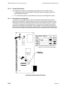
2.4.2.6 Opto-Isolated Fault Output Connection
WARNING Mains voltages are present in this instrument when power
is connected. De-energise before opening front cover.
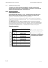
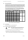
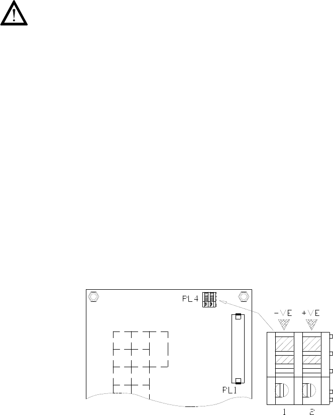
Plug PL4 is used for the FAULT output. A 2-core screened cable, capable of taking 1A and
30V is required and is connected into its 2-way terminal block such that:
Note: No fault present = Short circuit, < 1.1V at 1 Amp
Fault present = Open circuit, < 1 mA at 30V
The positive output conductor terminates in socket PL4 pin 2.
The negative output conductor terminates in socket PL4 pin 1.
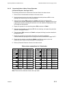
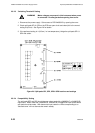
Gain access to PCB 24680515 and connect the FAULT output cable as follows:
1. Prepare the FAULT output cable to give a stress-free run to PL4 on PCB 24680515.
Fault output wiring must not share cables with power inputs or electrode inputs, and is
considered good practice to twist the FAULT cable pairs together.
2. Use a good quality RF cable gland, and ensure there is a good annular (ring shape)
connection with the screen.
3. Prepare the conductor ends and connect the conductors into their respective terminal.
Check the cable run and tie it to the present loom. Tighten the gland nut (if applicable)
and close the instrument front cover.
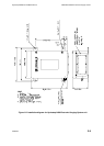
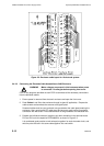
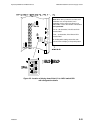
Part of Display Board showing PL4
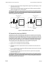
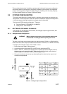
If the installation is adversely affected by the operation of nearby equipment, then re-routing
the cables to these instructions should improve the performance:
Avoid bundling the cables from both channels together
Ensure that cables run against earthed metalwork where possible
Use screened cables for all connections, making sure that a good annular (ring shape)
connection is made with a good quality RF cable gland
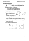
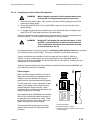
Electrode, Relay, and Analogue Output wiring on the left-hand (enclosure hinge) side should
not be pressed hard against the ribbon cables, but instead run forward of the connectors and
away from the side of the casing. Do not run the wiring over the PCB.
Wiring on the right-hand (enclosure catch) side should be tucked into the back of the enclosure,
next to the connectors, and as close to the casing as possible and below the vase plate level.
Supply wiring should be run close to the metalwork, forward of the signal wiring, but never
along the left-hand (hinged) side of the enclosure near the ribbon cables.
The ribbon cables must be run under the back plate and up the left-hand (hinged) side of the
enclosure, and secured by using clips (supplied).