


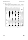
Hydrastep 2468CB and 2468CD Manual Delay Relay Output Board Option
24685034
3b-5
3B.2.3 ELECTRICAL INSTALLATION
This sub-section deals with the output of the states of the four relays. Two 8-way sockets are
provided with each output board through which the relay outputs are delivered to their
external destinations.
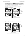
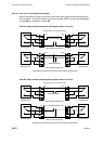
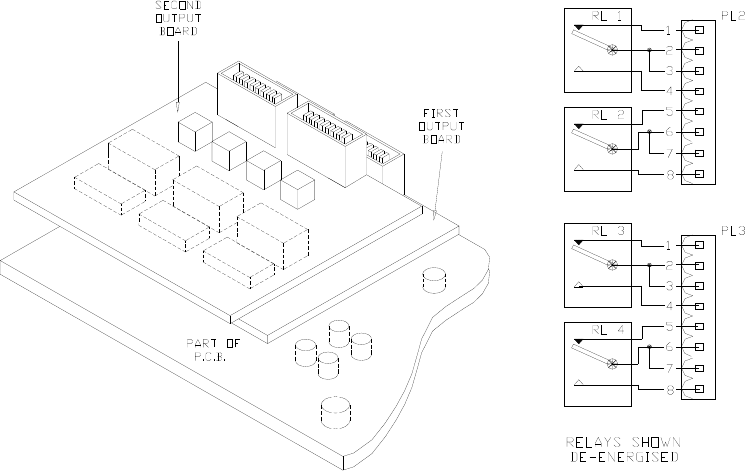
3b.2.3.1 PCB Interconnections
Signal interconnection between the input board (PCB1) and the output board (PCB 9) is
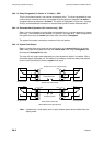
direct via the SK1/PL1 12-way Berg connectors. When two output boards are fitted, the top
board’s plug PL1 engages in the lower board’s SK1.
3b.2.3.2 Relay Output Connections
The relay outputs can be taken out of the enclosure via the gland plate (if used) or along with
the other cables in suitable trunking.
Use screened cables for all connections, making sure a good annular (ring shape) connection
is made with a good quality RF cable gland. The run must be stress-free, and it is considered
good practice to twist relay pairs together.
Since the output board is mounted on top of the input board, the routing of the relay cabling
should take the same kind of formation as the electrode cabling, but separated from it as far
as practical. The cable should be arranged such that the cables do not lie across any of the
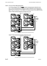
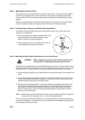
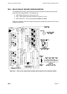
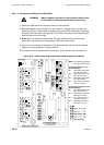
PCBs. The layout and plug pin details of the two plugs on the relay board is given in the
diagram on the right, with the relay contacts shown in their de-energised state.
When two output boards are fitted, the output terminals of the uppermost output board are
offset towards the centre of the input board.
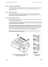
View illustrating mounted positions of dual
delay relay output boards
Relay output PCB
connectors