


Delay Relay Output Board Option Hydrastep 2468CB and 2468CD Manual
3b-10 24685034
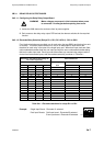
3b.3.1.7 Configuring the Delay Circuit Split Pads
WARNING Mains voltages are present in this instrument when power
is connected. De-energise before opening front cover.
1. Isolate the 2468 electronics enclosure from its power supplies.
2. Split pad bridging may be carried out in-situ, however it may be easier to remove the
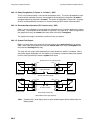
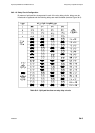
board from the unit. Gain access to the delay relay output PCB and bridge the required
split pads (see Table 3b.2 and Figure 3b.2) with solder, ensuring that the remaining split
pads are open-circuit and clean.
3. Note: When two output boards are fitted, the upper board will have to be removed
temporarily to give access to the split pads of the lower output board.
4. Carry out any necessary re-assembly on the output board(s) and test that the required
delay on the relay operations is being achieved.
5. If no further work is required inside the enclosure, close and secure the enclosure lid.
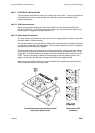
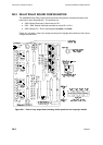
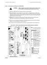
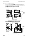
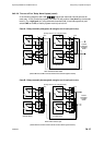
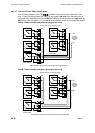
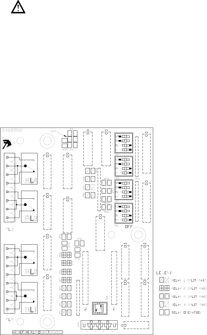
Figure 3b.2 - View of delay relay output board showing split pad positions
Note: The following split pads
must be set as follows:
For Delayed Operation of the
Nominated Relay:
RL1 SP21 bridged with solder
SP15 open-circuited
RL2 SP22 bridged with solder
SP20 open-circuited
RL3 SP23 bridged with solder
SP1 open-circuited
RL4 SP24 bridged with solder
SP6 open-circuited
For No Delayed Operation of the
Nominated Relay:
RL1 SP15 bridged with solder
SP21 open-circuited
RL2 SP20 bridged with solder
SP22 open-circuited
RL3 SP1 bridged with solder
SP23 open-circuited
RL4 SP6 bridged with solder
SP24 open-circuited