


2468CB & 2468CD Dual Power Supply Version Hydrastep 2468CB and 2468CD Manual
2-2 24685034
2.5.2 DISPLAY BOARD 24680515 ............................................................... 2-20
2.5.2.1 Link LK1 Setting .................................................................... 2-20
2.5.2.2 Configuring the ‘Number of Electrodes’ Switch .................... 2-20
2.5.2.3 ‘Switching Threshold’ Setting ................................................ 2-22
2.5.2.4 ‘Compatibility’ Setting ............................................................ 2-22
2.6 FAULT ANALYSIS & CORRECTIVE ACTION ....................................... 2-23
2.6.1 COMPONENT REPLACEMENT .......................................................... 2-30
2.6.1.1 Removing the Input Board (24680501 or 24680516) ........... 2-30
2.6.1.2 Refitting the Input Board ....................................................... 2-30
2.6.1.3 Removing the Display Board 24680515 ............................... 2-30
2.6.1.4 Refitting the Display Board ................................................... 2-30
2.6.2 PARTS LIST - HYDRASTEP 2468 CB & CD VERSIONS ................... 2-31
2.7 SPECIFICATION ..................................................................................... 2-32
Illustrations
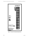
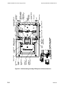
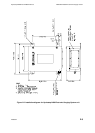
Figure 2.1: Outline drawing showing PCB layout and interconnections ............................... 2-4
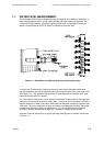
Figure 2.2: Installation diagram for Hydrastep 2468 Electronic Gauging System unit ......... 2-9
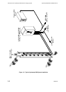
Figure 2.3: Enclosure cable layout for 16 electrode system ............................................... 2-12
Figure 2.4: Voltage Selection (240V or 110V) .................................................................... 2-14
Figure 2.5- Location of display board links LK1 to LK5 & switch SW1 with configuration…..….
details………………………………………………………………………………….2-21
Figure 2.6- Split pads SP1, SP2, SP5 & SP6 locations and settings ................................. 2-22
Tables
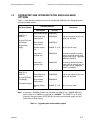
Table 2.1 - Analogue output configurations ...................................................................... 2-17
Table 2.2 - Number of electrodes being displayed ........................................................... 2-20
Table 2.3 - Fault analysis/corrective action chart ............................................................. 2-23