


Hydrastep 2468CB and 2468CD Manual Delay Relay Output Board Option
24685034
3b-7
3B.3.1 DELAY RELAY OUTPUT BOARD
3b.3.1.1 Configuring the Delay Relay Output Board
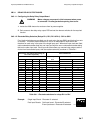
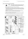
WARNING Mains voltages are present in this instrument when power
is connected. De-energise before opening front cover.
1. Isolate the 2468 electronics enclosure from its power supplies.
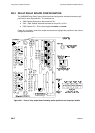
2. Gain access to the delay relay output PCB and set the relevant switches for the required
function.
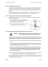
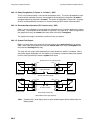
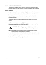
3b.3.1.2 Electrode/Relay Selection (Relays RL1, RL2, RL3 & RL4) - SW1 to SW4
Four identical switches are provided, one for each relay (but see SW6) each having four sets
of contacts. This allows coded selection for one of 16 electrodes for each switch and
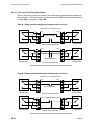
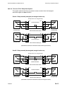
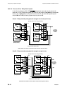
therefore for each relay in the case of the single input card. When dual input cards are fitted,
odd numbered electrodes feed into one input card with the even numbered electrodes being
fed into the other input card. Each input card then offers any mounted relay output card the
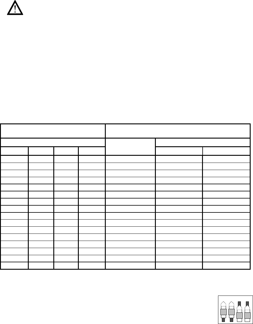
choice from its electrode inputs, with the resultant selectivity as shown in Table 3b.1.
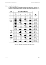
Switch SW1, 5W2, 5W3 or 5W4 Settings for
RL1 to RL4 respectively
Electrode Selection
Switch Contacts One Input Two Input Cards
1 2 3 4 Card Odd I/P Card Even I/P Card
On On On On 1 1 2
Off On On On 2 3 4
On Off On On 3 5 6
Off Off On On 4 7 8
On On Off On 5 9 10
Off On Off On 6 Ii 12
On Off Off On 7 13 14
Off Off Off On 8 15 16
On On On Off 9 17 18
Off On On Off 10 19 20
On Off On Off 11 21 22
Off Off On Off 12 23 24
On On Off Off 13 25 26
Off On Off Off 14 27 28
On Off Off Off 15 29 30
Off Off Off Off 16 31 32
Table 3b.1 - Electrode selections for relays RL1 to RL4
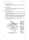
Example: Single Input Board - Electrode 13 selected.
Dual Input Boards: Odd input board - Electrode 25 selected
Even input board - Electrode 26 selected.
1
2
3
4
OFF