


Hydrastep 2468CB and 2468CD Manual 2468CB & 2468CD Dual Power Supply Version
24685034 2-19
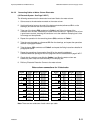
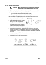
2.5.1.4 Configuring the Unit to Detect Electrode Error
WARNING Mains voltages are present in this instrument when power
is connected. De-energise before opening front cover.
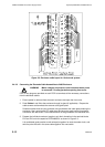
1. Disconnect the power supply. Gain access to the input PCB by opening the cover and
removing the option board.
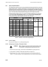
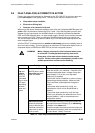
2. Check split pads SP6 & SP7 on the input PCB are open circuit and clean (this is the
default setting).
3. To change the electrode error threshold value or to disable the feature, bridge the split
pads SP6 or SP7 with solder as shown in the table above.
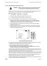
Repeat the procedure used in configuring the first input board to set up the remaining input
board as required. This concludes the configuration on the input boards.
WARNING Bridging SP7 will disable the electrode fault alarm. In this
condition, a fouled electrode in water will not be detected.
This is of particular importance when electrodes are used
for low level alarm or cut off.
By bridging split pad 6 on the input board, the conductivity fault detection level will be increased
from 104S (normal) to 300S (high). This may be sufficient in some cases, but not all.
Factory modifications are available to further increase this level to 800S, 1600S or
2000S. At each of these stages, the measuring sensitivity of the Hydrastep system is
reduced, so the most appropriate level should be chosen, not the highest. Contact your local
representative for further details.
Note that input boards that have been modified are marked with the number 24680229A and
the conductivity level that is acceptable.
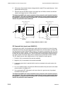
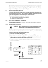
Offset voltages:
When an offset voltage is present on the return
signal and is relatively high compared to the ac
voltage, it may have the effect of lifting the
square wave to the water/steam switching point.
This will cause one, or more, electrodes to flash
rapidly on the display as the detection circuits
alternate between steam and water. When
combined with the problem described above, the
display becomes very confusing.
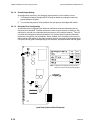
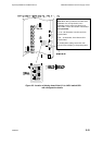
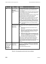
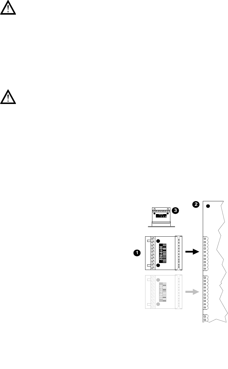
Input adapter boards (24680523A) are available
which fit into the electrode cable connectors on
the input board (see inset picture, right). These
have series capacitors in the return side of the
cables, blocking any dc offset voltages.
The electrode cable then plugs into the Input
Adapter Board instead of the electrode cable
connector.
1. Input Adapter Board.
2. Input Board (Partial Top View).
3. Adapter plugged into electrode cable connector
(Horizontal View).