


Remote Display Options 24683B, C & D Hydrastep 2468CB & 2468CD Manual
4-10 24685034
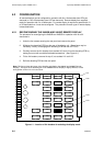
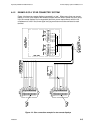
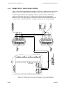
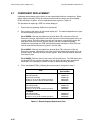
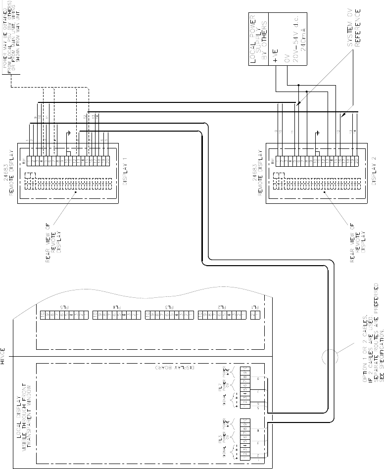
4.4.3 EXAMPLE OF A `DAISY CHAIN' SYSTEM
Figure 4.5 shows two remote displays connected in a `daisy chain'. Where more than one remote
display is in use, local supplies with isolated outputs must be used to power the extra unit(s).
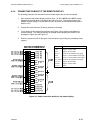
To prevent signal reflections from corrupting the data, it may be necessary to fit termination
resistors to the last unit in the chain. The resistor values should match the characteristic
impedance of the cable (120, typical). A termination resistor is connected between pins 3 and
4, and 17 and 18, on terminal block TB1. A suitable resistor to use is a ¼W metal film type.
Figure 4.5 - Daisy chain connection example for two remote displays