


Hydrastep 2468CB and 2468CD Manual 2468CB & 2468CD Dual Power Supply Version
24685034 2-25
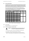
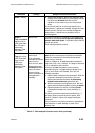
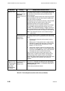
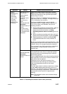
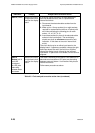
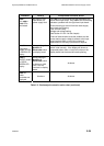
Indication Fault(s) Analysis and Corrective Action
State 1 (contd.)
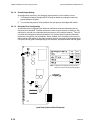
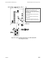
3. Insert these sockets in place of the electrode cable
sockets in the input boards, the level display should
now show an all steam state and no fault
indication. If this does not occur an internal fault
exists.
The circuit fault may be on either input board or the
display board. If spares are available, change the input
board first and if the fault is not rectified change the
display board. If spares are not available, call the
service engineer.
State 2
Top and bottom
halves of fault
LED illuminated
No LED pairs
alternating
between water
and steam
Internal fault This state is indicating a fault which is not related to an
electrode error because no LED pairs are alternating
between water and steam. It is therefore likely that an
internal fault exists.
Follow same procedure as above.
State 3
Top half of fault
LED illuminated
One or more
LED pairs
alternating
between water
and steam
Electrode wiring or
internal fault
Even numbered
electrode connection
open-circuit or
short-circuit to earth
Affected electrode
alternates between
water and steam.
Incorrect wiring,
broken connection or
damaged cable
assembly
Check that all even numbered electrodes indicating
water have the correct pair of conductors connected.
Check the connections to the left hand input board.
Rectify wiring if incorrect.
Check ac voltage on all even electrodes immersed in
water with a true r.m.s. voltmeter. A voltage of less than
0.1V ac indicates a fault condition.
If wiring to all even electrodes is correct and the
electrodes still give a voltage reading of greater than
0.1V ac and a fault is still indicated, carry out the
following procedure:
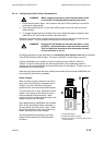
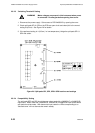
1. Remove both conductors from electrode 2. With the
conductors isolated from each other, the level
display should show electrode 2 as alternating
between water and steam (green and red).
2. With the conductors touching each other, the level
display should show electrode 2 as being in steam.
3. Repeat operations 1 and 2 for all affected even
numbered electrodes until a faulty indication is
found.
The above procedure checks the electrode wiring. If
the display does not show the correct results, then
check for a break in either of the suspect electrode
conductors.
Carry out repair to any faulty connection or substitute a
new conductor or cable assembly in place of the
defective item.
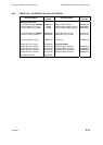
Table 2.3 - Fault analysis/corrective action chart (continued)