2468CB & 2468CD Dual Power Supply Version Hydrastep 2468CB and 2468CD Manual
2-12 24685034
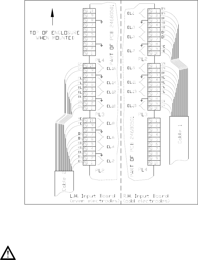
Figure 2.3: Enclosure cable layout for 16 electrode system
2.4.2.3 Connecting the Electrode Cable Assemblies to 2468 Enclosure
WARNING Mains voltages are present in this instrument when power
is connected. De-energise before opening front cover.
Four 10-way plugs are provided on each PCB1 to terminate all the necessary connections
from the electrode cables.
1. Ensure power is removed from electronic enclosure and open the front cover.
2. Feed Cables 1 and 2 into the enclosure through its gland (if applicable). Prepare the
cable screens and terminate the screens at the gland plate.
Screened cables must be used, and each one grounded at the cable gland entering the
enclosure. Use a good quality RF cable gland and ensure a good annual (ring shape)
connection with the screen. The screens should not be grounded at the electrode end.
3. Prepare the individual conductor lengths to suit their orientation in the terminal blocks
PL2 and PL3 on their respective PCB 24680501 as shown in Figure 2.3.
It is considered good practice to twist wire-pairs together for each electrode circuit, and
twist the pairs that are in the same cable together into one bundle.


