


Installation Procedures Hydrastep Pressure Parts
24675030
2-5
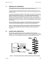
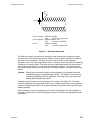
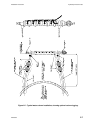
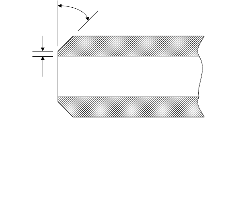
Figure 2.1 - Universal weld profile
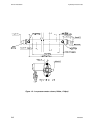
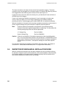
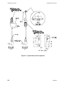
The Steam and Water connections on the water column must be set to position the water
column at the correct level before they are welded in place, Figure 2.2 gives an example of
the water column installation. Normally, the water level of the drum will be between
electrodes 6 and 7 for a twelve port water column. However, due to the physical or operating
conditions, this could be offset. The steam leg must slope downwards to the water column
with a minimum gradient of 1 in 50 to ensure condensate circulation. The water leg must
slope downwards to the drum to prevent water from being trapped at the bottom of the water
column.
Caution: Care must be exercised to ensure that the pipework is not allowed to take the
unsupported weight of a standard water column. The weight of the column and
its associated pipework are fully supported - there must not be any load on the
welded pipework attachment points.
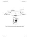
Installation should commence with the support of the column, see Figure 2.3. The water
column is attached to the supports which will carry the weight of the water column and allow
it to be accurately aligned with the drum steam and water connections before and during the
welding operation.
After the welding to the connecting pipework, valves and the fitting of the drain pipework is
complete, a further check on the level alignment must be carried out and adjustments made,
if necessary.
45°
1.5mm
For HP (210 bar) Material: SA106B
Size: 1" N.B, Sch. 160 pipe dim.
For HP (300 bar) Material: SA479 - 316
Size: 1" N.B, Sch. XXS PPE
For LP Material: SA106B
Size: 1" N.B, Sch. 80 pipe dim.