


Hydrastep 2468CB and 2468CD Manual 2468CB & 2468CD Dual Power Supply Version
24685034 2-23
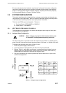
2.6 FAULT ANALYSIS & CORRECTIVE ACTION
Faults in the system will generally be indicated by the YELLOW LED on the front panel and
by the fault output on the display board. The main faults, which are catered for, are:
Water above steam condition
Electrode or Wiring fault
Detection of an internal circuit fault
When any of the above mentioned conditions exist within the Hydrastep 2468CB system, the
yellow LED is illuminated to indicate the FAULT state. Since the electrode inputs are split
between the two input boards, the ALARM indicator is configured to differentiate between
ODD and EVEN electrode faults. An opto-coupler output, normally short-circuited, becomes
open-circuited on a FAULT state, providing an ALARM indication output for external use.
The current output indicates an alarm condition by a 0.5Hz waveform superimposed on the
main analogue signal.
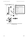
A further FAULT is indicated when the number of electrodes switch on the display board is
set to an invalid number. This error brings up an alternate LED illumination display, that is a
chequered display of GREEN and RED LEDs on the two front panel columns.
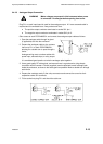
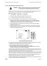
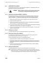
WARNING Mains voltages are present in this instrument when power
is connected. De-energise before opening front cover.
Some parts of the water column and electrodes may be
very hot. Please ensure parts are adequately cooled or that
suitable precautions are taken before handling.
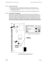
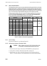
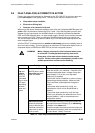
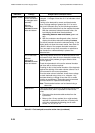
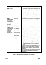
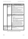
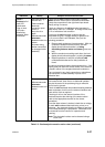
Indication Fault(s) Analysis and Corrective Action
State 1
Top and
bottom
halves of
fault LED
illuminated
One or more
LED pairs
alternating
between
water and
steam
Water conductivity.
All LED pairs in water
alternating between
water and steam.
Check ac voltage on all electrodes immersed in
water with a true r.m.s. voltmeter. If several of the
immersed electrodes show a voltage of less than
approximately 0.1V ac then very high water
conductivity is probable.
Check water column installation is correct; sloping
pipework and insulation details. Make sure that
there is sufficient condensate flow through the
column.
If the normal water conductivity is high, the
electrode error circuit can be de-sensitised or
disabled.
If the normal water conductivity is still too high
(40mV ac at electrode), the electrode error circuit
must be disabled – refer to the electrode error
configuration section.
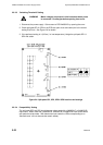
Water above steam,
caused by electrode
wiring or internal fault
Electrode connection
open-circuit or short-
circuit to earth
The electrode channel(s) causing the problem will
be evident from the unit display by an alternating
indication in the steam area.
Check the suspect electrode(s) has the correct pair
of conductors connected, check the connections to
the input board. Rectify if incorrect.
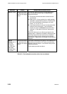
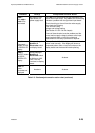
Table 2.3 - Fault analysis/corrective action chart