


Hydrastep 2468CB and 2468CD Manual 2468CB & 2468CD Dual Power Supply Version
24685034 2-13
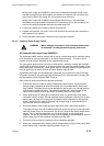
Wiring to the ‘hinge-side’ 24680501 board (even-numbered electrodes) should not be
pressed hard against the ribbon cables, but instead run forward of the connectors and
away from the side of the casing. Do not route them over the board.
Wiring to the ‘catch-side’ 24680501 board (single channel set-up / odd-numbered
electrodes) should be tucked into the back of the enclosure, next to the connectors, as
close to the casing as possible and below the base plate level.
4. Fit the free sockets into the terminal blocks PL2 and PL3.
5. Prepare the conductor core ends, fit the crimp terminals and connect the conductors to
their respective free sockets.
6. Ensure that both cables have a stress-free run inside the enclosure.
2.4.2.4 Hydrastep Power Supply Cables
WARNING Mains voltages are present in this instrument when power
is connected. De-energise before opening front cover.
AC Powered Units (input board 24680501)
The Hydrastep 2468C must be installed with a fuse or circuit breaker with a maximum rating
of 5A mounted as close as practicable, in an easily reached location. The fuse or circuit
breaker must be uniquely identified as the disconnecting device.
The cable gland used must have an inlet or bushing with a smoothly rounded bell-mouthed
opening with a radius of curvature of at least one and a half times the overall diameter of the
mains cable fitted. Alternatively, a fixed guard made of insulating material protruding beyond
the inlet opening by at least five times the cable diameter may be used.
A shielded power cable, and shielded signal cables with the connection to the unit through
RF glands mounted on the gland plate should be used for all units that need to comply with
the requirements of the European EMC Directive.
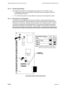
Gain access to each input board and proceed as follows:
1. Ensure that the mains cable is safely isolated before starting work, and ensure that
enough length is prepared to install it according to the route described in Step 2 and
Step 3 below. The power inlet must be dedicated to that function only. No signal wiring
must share the power inlet cable. Two separate protected AC mains circuits (of the
same electrical phase) may be provided in a suitably rated multi-way cable.
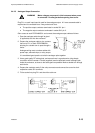
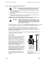
2. Use a good quality RF cable gland, and ensure there is a good annular (ring shape)
connection with the screen. A ferrite (supplied) must be attached inside the unit to each
supply input, as close to the inlet gland as possible. Make a double-turn through each
ferrite – ensure that the cable is prepared with enough length to accommodate this –
and have the entire run stress-free.
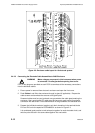
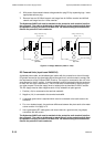
3. Route the cables to both boards along the right-hand (catch) side of the enclosure.
The supply wiring to the even-numbered electrode boards should run up the right-hand
side and across the top of the enclosure. Do not run it close to the display board ribbon
cables. The run must be stress-free, and it is good practice to twist power pairs
together. The use of a self-adhesive cable tie (not supplied) is recommended to hold the
power cables close to the metalwork and away from the PCB.
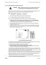
4. Connect the live and neutral conductor to their respective terminals.
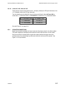
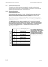
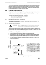
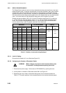
5. Check the voltage setting by checking which voltage selection plug is fitted (set to 240V
at the factory) and, if required, adjust as guided in
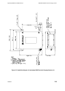
Figure 2.4.