


180
MU128 Plug-in System
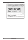
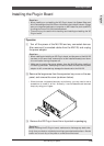
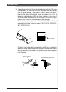
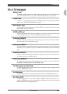
4 Insert the board along the guide rails about two-thirds of the way
inside the MU128, with the connector side face down and toward
you (as shown below). Make sure to insert it slowly and gently,
keeping the edges of the board inside the proper guide rails, as
shown in the illustration. With the board in place, plug in one of
the three cable connectors to the connector on the XG Plug-in
board. Any one of the cable connectors can be used.
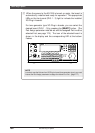
The logical board assignment in the MU128 (PLG-1 - 3) is set
automatically to the following order: 1) PLG100-VL, 2) PLG100-
DX, 3) PLG100-VH.
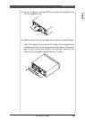
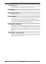
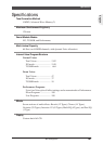
Carefully plug in the cable connector to the XG Plug-in connector
as shown below, matching the two notches on the cable connector
with the sockets on the board. Firmly press the connectors together
until they lock.
About Plug-in System
MIDI
THRU
OUT
IN-A
IN-B
HOST SELECT
MIDI
Mac
PC-2 PC-1
TO HOST DC IN
OUTPUTINPUT
L
R
SER NO.
Guide rail
Plug-in board
Insert the board along
one of these rails.
XG Plug-in board
Cable connector
XG Plug-in connector
Notch
Press the connectors together until
the two notches lock into the sockets.