


128
MU128 Multi Mode
Filter Parameters
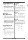
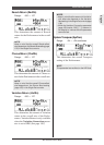
LPF Cutoff Frequency (LPF Cutoff)
Range: –64 — +63 (XG mode), 000 —
127 (TG300B mode)
This determines the cutoff frequency of
the low pass filter (LPF) for the selected
drum sound. The LPF filters out frequen-
cies higher than the cutoff point and
“passes” the lower frequencies. Lower
cutoff values create a deeper, more
rounded tone, while higher values create
a brighter tone. (For more information,
see LPF Cutoff Frequency on page 112.)
LPF Resonance (LPF Reso)
Range: –64 — +63 (XG mode), 000 —
127 (TG300B mode)
This determines the amount of filter reso-
nance or emphasis of the LPF Cutoff Fre-
quency above for the selected drum
sound. Higher values make the filter ef-
fect more pronounced and stronger, cre-
ating a resonant peak around the cutoff
frequency. (For more information, see
LPF Resonance on page 112.)
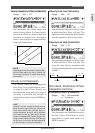
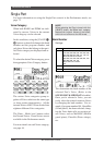
Velocity LPF Cutoff Sensitivity (VelLPFSens)
Range: –16 — +16
This determines the degree to which the
LPF Cutoff Frequency for the selected
drum sound changes in response to ve-
locity. In other words, you can shift the
LPF Cutoff Frequency of the filter up or
down (and thus change the timbre of the
sound) depending on how hard or soft you
play the keys of a connected keyboard.
Positive values raise the LPF Cutoff Fre-
quency and negative values lower it. A
value of 00 results in no frequency
change, whatever velocity is received.
Multi Edit Mode
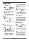
Chorus Send (Cho Send)
Range: 000 — 127
This determines the level of the selected
drum sound that is sent to the Chorus ef-
fect. A value of 000 results in a completely
“dry” drum sound, no matter how much
Chorus is applied to the Drum Part.
NOTE
Keep in mind that the Chorus effect must be
properly enabled and set for this parameter to
work as intended. (See page 88.) Also, the pa-
rameters Chorus Send in Single Part control
(page 107) and Chorus Return in All Part con-
trol (page 109) must be set to appropriate val-
ues.
Variation Send (Var Send)
Settings: off, on (when Variation Con-
nection is set to INS);
000 — 127 (when Variation
Connection is set to SYS)
When the Variation Connection parameter
(page 150) is set to “INS,” this determines
whether the Variation effect is applied to
the selected drum sound or not.
When the Variation Connection parameter
(page 150) is set to “SYS,” this determines
the level of the selected drum sound that is
sent to the Variation effect.
A setting of “off” or “000” results in no
Variation effect being applied to the drum
sound.
NOTES
• Keep in mind that the Variation effect must
be properly enabled and set for this param-
eter to work as intended. (See page 90.)
• When the Variation Connection parameter
(page 150) is set to “INS,” the “Variation Send”
parameter in the Single Part controls (page
108) must also be set to on in order to use
the Variation effect.
• When the Variation Connection parameter
(page 150) is set to “SYS,” the parameters
“Variation Send” in the Single Part controls
(page 108) and “Variation Return” in the All
Part controls (page 110) must be set to ap-
propriate values.