


MU128 Performance Mode
139
English
Assignable Controller Parameters
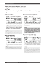
Assignable Controller 1 Control
Change Number (AC1 CC No.)
Same as the corresponding parameter in
the Multi Edit mode (page 124), with the
exception that AC1 in the Performance
mode can also control LFO filter modu-
lation (see Assignable Controller 1 LFO
Filter Modulation Depth below).
Assignable Controller 1 Filter Control
(AC1 FilCtrl)
Same as the corresponding parameter in
the Multi Edit mode. (page 124.)
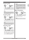
Assignable Controller 1 Amplitude
Control (AC1 AmpCtrl)
Same as the corresponding parameter in
the Multi Edit mode. (page 125.)
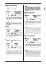
Assignable Controller 1 LFO Filter
Modulation Depth (AC1LFOFMod)
Range: 000 — 127
This determines the degree to which As-
signable Controller 1 (AC1) affects the
LFO modulation of the Filter. This cre-
ates a regular and continuous “wah-wah”
or filter sweep effect. The higher the
value, the greater the LFO filter modula-
tion. (The control number used for AC1
is set in the Assignable Controller 1 Con-
trol Change Number parameter above.)
Modulation Wheel — LFO Filter
Modulation Depth (MW LFOFMod)
Range: 000 — 127
This determines how widely the Filter
(page 111) is modulated by the LFO (low
frequency oscillator). This is generally
controlled from a modulation wheel on a
MIDI keyboard, and depending on the
Voice used, it creates a “swoosh” or
“wah-wah” filter sweep effect. Higher
values result in deeper filter modulation,
creating a more pronounced filter sweep
effect.
Pitch Bend
Pitch Bend Control (PitBndCtrl)
Same as the corresponding parameter in
the Multi Edit mode. (page 123.)
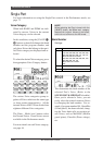
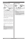
A/D Part
A/D Part
Settings: off, on
This determines whether A/D Parts are
enabled for the Performance or not. When
set to “on,” Parts 3 and 4 are automati-
cally set as A/D Parts (A/D1 and A/D2).
HINT
You can use the MU128 strictly as an effect
processor for the A/D input (for example, your
guitar or microphone) by Soloing the appro-
priate A/D Part (A/D1 or A/D2).
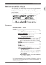
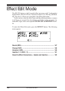
Performance Edit Mode