


59
Chapter 2: Task Guide
Formatting Labels for Logic Analyzer Probes
• LVCMOS 1.5v -- The threshold level is +0.75 volts.
• LVCMOS 1.8v -- The threshold level is +0.90 volts.
• LVCMOS 2.5v -- The threshold level is +1.25 volts.
• LVCMOS 3.3v -- The threshold level is +1.65 volts.
• CMOS 5.0v -- The threshold level is +2.50 volts.
• ECL -- The threshold level is -1.3 volts.
• LVPECL -- The threshold level is 2.00 volts.
3. If you don't want the change to apply to all pods, deselect the checked box
next to Apply settings to all pods.
4. Select the Close button.
User Defined
When User Defined is selected, the threshold level is selectable from -
6.0 volts to +6.0 volts.
NOTE: The logic analyzer requires a minimum voltage swing of 500 mV at the probe
tip to recognize changes in logic levels.
NOTE: The threshold voltage specified also applies to the pod's clock input.
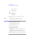
To assign probe channels to labels
The logic analyzer lets you assign names (labels) to logic analyzer
channels so that it's easier to set up triggers and interpret the captured
data when displayed.
Typically, you give labels the names of the buses and signals in the
device under test that are are being probed.
1. In the Format tab, select a label button, and either:
• Choose the Rename command, enter the label name, and select the OK
button.