


28
Chapter 1: Getting Started
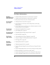
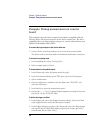
Example: State measurement on counter board
Example: State measurement on counter board
This example uses the demo counter board that is supplied with the
Making Basic Measurements kit as the device under test. The kit is
supplied with every logic analysis system, or can be ordered from your
Agilent Technologies Sales Office.
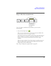
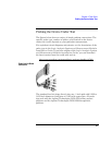
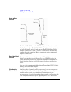
To connect the logic analyzer to the device under test
1. Connect Pod 1 of the logic analyzer to J1 on the demo counter board.
The demo counter board has built-in terminations and header connectors.
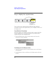
To choose the sampling mode
1. In the Sampling tab, choose State Mode.
2. In the Clock Setup, using the Master only mode, specify the rising edge of
the J clock as the sampling clock.
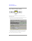
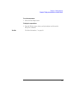
To format labels for the probed signals
1. In the Format tab, select the button under the pod 1.
2. In the Pod threshold dialog, select TTL; then, select the Close button.
3. Select a label button.
4. Choose the Rename command, enter the label name "SCOUNT", and
select the OK button.
5. In the label row, select the button under pod 1.
6. Choose the "........********" standard label assignment to assign the lower 8
bits of pod 1 to the "SCOUNT" label.
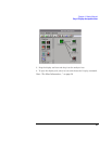
To define the trigger condition
1. In the Trigger tab, and in the Trigger Functions subtab, choose the "Find
pattern n times" trigger function, and select the Replace button.
2. In the Trigger Sequence portion of the Trigger tab, enter "15" in the
occurrence count field, and enter enter "FX" in the label value field.