


33
Chapter 2: Task Guide
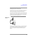
Probing the Device Under Test
Probing the Device Under Test
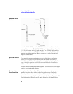
The figures below shows a variety of simple probing connections. The
specific probe type, number of probes, and location on the device
under test circuit depends on your particular measurement.
For equivalent circuit diagrams and pinouts, see the description of the
probe type in the Logic Analysis System and Measurement Modules
Installation Guide. If you have misplaced the Logic Analysis System
and Measurement Modules Installation Guide, you can download
the latest version from the world-wide web at:
http://www.cos.agilent.com/manuals/logic_analyzers.html#la_16700b
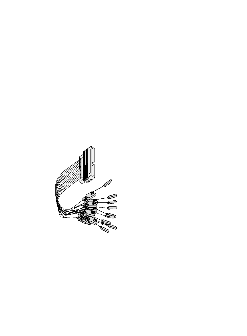
Probe Lead-to-Board
Connection
The standard lead set plugs directly into any .1-inch grid with 0.026 to
0.033-inch diameter round pins or 0.025-inch square pins. All probe
tips work with the Agilent Technologies 5059-4356 surface mount
grabbers and the Agilent Technologies 5959-0288 through-hole
grabbers.