


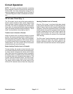
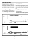
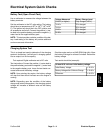
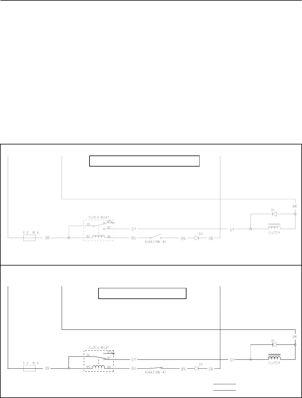
Electric Clutch Circuit (Fig. 3)
The electric clutch circuit is used on the ProCore to pro-
vide current for the electric clutch which rotates the cor-
ing crankshaft. This circuit is composed of the aeration
#3 proximity switch, the clutch relay, the electric clutch
and diode D3. The electric clutch circuit relies on the op-
eration of the ”OK to lower” circuit for completing the
clutch circuit (See OK to Lower Circuit in this section).
Electric clutch circuit protection is provided by fuse F2.
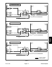
Not Aerating (Clutch not Engaged)
Whenever the coring head is in the raised position, the
aeration #3 proximity switch is open and the clutch relay
is not energized. The electric clutch will not be energized
so rotation of the coring crankshaft does not occur.
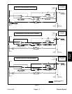
Aerating (Clutch Engaged)
The clutch relay will be energized as the coring head is
lowered to the point when the aeration #3 proximity
switch closes. This closed proximity switch provides a
complete circuit if the ”OK to lower” circuit is closed.
Once the clutch relay is energized, current is provided
to the clutch and rotation of the coring crankshaft be-
gins.
The clutch will continue to be energized until either:
A. The coring head is raised which opens the aera-
tion #3 proximity switch.
B. The “OK to lower” circuit opens (e.g. the operator
releases the traction lever while aerating).
GROUND
SWITCH
TO
CIRCUIT
CLUTCH CURRENT
GROUND
SWITCH
TO
CIRCUIT
(HEAD LOWERED)
(ENERGIZED)
(ENERGIZED)
(ENERGIZED)
TO IGNITION
TERMINAL ”L”
OK TO LOWER
NOT AERATING (CLUTCH NOT ENGAGED)
CONTROL CURRENT
TO IGNITION
TERMINAL ”L”
OK TO LOWER
AERATING (CLUTCH ENGAGED)
(NOT ENERGIZED)
(NOT ENERGIZED)
Figure 3
Electrical System
Page 5 – 6
ProCore 648