


ProCore 648 Hydraulic SystemPage 4 – 21
Procedure for Coring Head Raise/Lower Relief (R1)
Pressure Test:
1. Make sure hydraulic oil is at normal operating tem-
perature by operating the machine for approximately 10
minutes.
2. Park machine on a level surface with the coring head
fully raised. Make sure engine is off and the parking
brake is engaged.
3. Read Precautions For Hydraulic Testing in this sec-
tion.
CAUTION
Operate all hydraulic controls to relieve system
pressure and avoid injury from pressurized hy-
draulic oil.
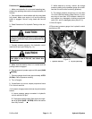
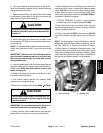
4. Connect pressure gauge to the hydraulic control
manifold G1 port quick fitting (Fig. 14).
5. Remove rear hood (see Operator’s Manual).
6. Locate and disconnect proximity switch #1. This
switch is secured to the switch mounting bracket located
on right rear frame plate.
7. Make sure that traction lever is in the neutral position
and the parking brake is engaged.
8. With proximity switch #1 disconnected, system pres-
sure will increase to relief (R1) pressure shortly after the
engine is started.
9. Start and run engine at full speed (3400 +
50 RPM).
Watch the pressure gauge and note pressure when the
relief valve (R1) opens.
10.Shut off engine. Record measured relief valve (R1)
pressure.
11. Pressure gauge should read approximately 1000
PSI (69 Bar).
12.If measured relief pressure is incorrect, adjust relief
valve (R1) as follows:
NOTE: Do not remove lift relief valve from the hydraulic
manifold for adjustment.
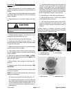
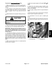
A. Remove the cap from the relief valve (Fig. 17).
B. If measured relief pressure is too high, decrease
relief valve pressure setting by using an allen wrench
to turn adjustment socket counterclockwise. A 1/8
turn on the socket will make a measurable change in
relief pressure.
C. If measured relief pressure is too low, check for
restriction in gear pump intake line or leakage in lift
cylinder. If pump intake line is not restricted and lift
cylinder is not leaking, increase the relief valve pres-
sure setting. Use an allen wrench and turn adjust-
ment socket clockwise. A 1/8 turn on the socket will
make a measurable change in relief pressure.
D. Reinstall cap on relief valve after adjustment.
E. Repeat steps 9 through 11 above until the relief
valve pressure setting is correct.
F. If the relief valve pressure setting cannot be ad-
justed to specification, the relief valve (R1), gear
pump or lift cylinder should be suspected of wear or
damage.
13.When testing is complete, disconnect pressure
gauge from the hydraulic manifold G1 fitting. Reconnect
proximity switch #1. Install rear hood.
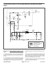
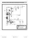
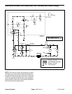
1. Hydraulic manifold
2. G1 port quick fitting
3. Relief valve (R1)
Figure 16
2
1
3
Figure 17
1. Relief valve cap 2. Adjustment socket
2
1
Hydraulic
System