


ProCore 648 Hydraulic SystemPage 4 – 25
Procedure for Traction Circuit Relief Pressure
Test:
1. Make sure hydraulic oil is at normal operating tem-
perature by operating the machine for approximately 10
minutes. Make sure that traction lever is adjusted to the
neutral position (see Operator’s Manual).
2. Park machine on a level surface with the coring head
fully raised. Make sure engine is off and parking brake
is engaged. Secure coring head with service latch.
3. Read Precautions For Hydraulic Testing in this sec-
tion.
4. Set the aerator spacing lever to the transport posi-
tion.
5. Make sure that hydraulic pump drive belt is adjusted
properly (see Operator’s Manual).
6. Lift or jack front of machine so front wheel is off the
floor. Support front of machine with jackstands or block-
ing.
CAUTION
Operate all hydraulic controls to relieve system
pressure and avoid injury from pressurized hy-
draulic oil.
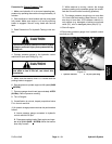
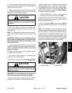
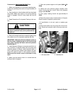
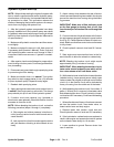
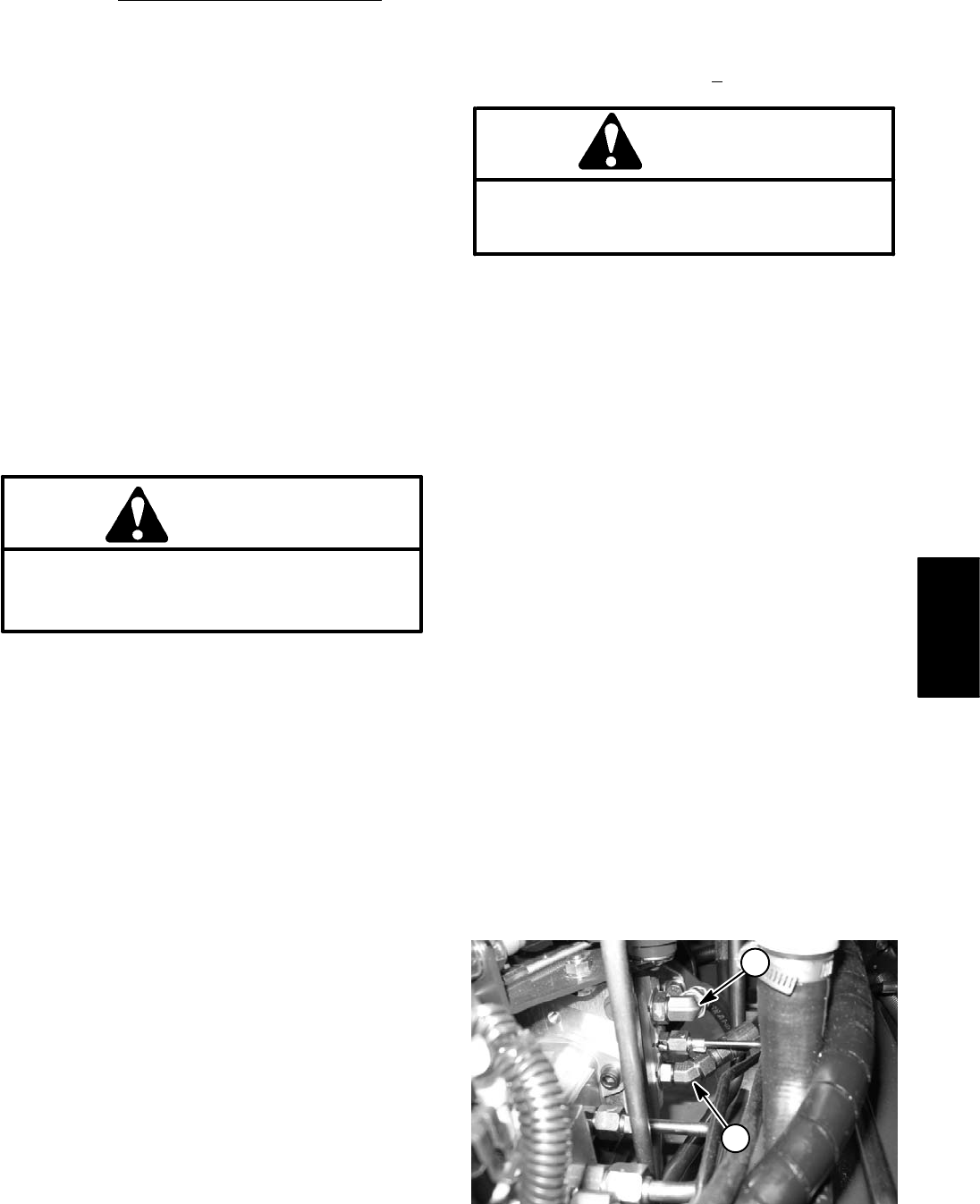
7. Clean hose fitting and disconnect appropriate hy-
draulic hose from fitting on the rear side of the traction
pump (Fig. 21):
A. For forward direction relief pressure test, discon-
nect hose from lower 45
o
fitting. NOTE: forward relief
pressure can also be measured with hydraulic tester
installed as described in TEST NO. 3: Traction (Pis-
ton) Pump Flow. Make sure flow control valve on the
tester is fully open.
NOTE: An alternate testing location for forward di-
rection relief would be at the hydraulic hose connec-
tion to the front wheel motor P1 port.
B. For reverse direction relief pressure test, discon-
nect hose from upper 90
o
fitting.
NOTE: An alternate testing location for reverse di-
rection relief would be at the diagnostic port on the
hydraulic tube between the rear wheel motors.
8. Install Tee–fitting with pressure gauge between the
traction pump and the disconnected hose.
9. Check and adjust the oil level in the reservoir after
connecting pressure gauge.
10.One person should operate the machine while
another person reads the gauge.
11. Make sure that parking brake is engaged. Start and
run engine at full speed (3400 +
50 RPM).
CAUTION
Use extreme caution when conducting test. The
front wheel of the machine will be trying to move
the machine.
12.Slowly move traction lever fully in direction of relief
valve to be tested (forward or reverse).
IMPORTANT: DO NOT hold system at relief for more
than 4 seconds.
13.Watch the pressure gauge and record pressure
when the traction circuit relief valve opens.
TESTER READING: pressure approximately 2900
PSI in both forward and reverse direction.
14.Release traction lever and turn off engine. Record re-
sults of hydraulic pressure test.
15.If traction pressure is too low, inspect relief valves in
piston (traction) pump (see the HYDRO–GEAR
BDP–10A/16A/21L HYDROSTATIC PUMPS SERVICE
AND REPAIR MANUAL at the end of this chapter).
Clean or replace relief valves as necessary as they are
not adjustable. If relief valves are in good condition, pis-
ton (traction) pump should be suspected of wear and in-
efficiency.
NOTE: Forward and reverse relief valves are identical.
Relief valves can be switched in piston (traction) pump
to help in identifying a faulty relief valve.
16.Disconnect Tee–fitting with pressure gauge from
pump fitting and hydraulic hose. Reconnect hose to
pump fitting.
1. Lower 45
o
fitting 2. Upper 90
o
fitting
Figure 21
2
1
Hydraulic
System