


Rev. B
ProCore 648 Hydraulic SystemPage 4 – 23
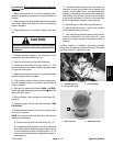
6. Lift or jack machine so all wheels are off the floor to
allow flow through the traction circuit. Support machine
with jackstands or blocking.
7. Attach a heavy chain to the rear of the machine frame
and something immovable in the shop to prevent the
machine from moving during testing.
CAUTION
Operate all hydraulic controls to relieve system
pressure and avoid injury from pressurized hy-
draulic oil.
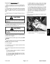
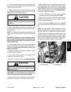
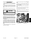
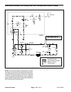
8. Clean hose fitting and disconnect hydraulic hose
from the lower 45
o
fitting on the rear side of the traction
pump (Fig. 19).
NOTE: An alternate testing location would be at the hy-
draulic hose connection to the P1 port of the front wheel
motor.
IMPORTANT: Make sure oil flow indicator arrow on
the flow meter is showing that the oil will flow from
the traction pump, through the tester and into the
disconnected hose.
9. Install hydraulic tester with flow meter and pressure
gauges in series with the traction pump and the discon-
nected hose. Make sure flow control valve on the
tester is fully open.
10.Check and adjust the oil level in the reservoir after
connecting hydraulic tester.
11. One person should operate the machine while
another person reads the tester.
12.Start and run engine at full speed (3400 +
50 RPM).
CAUTION
Use extreme caution when conducting test. The
wheels of the machine will be trying to move the
machine forward.
IMPORTANT: Do not rotate the traction pump trun-
nion shaft clockwise (reverse) during testing.
13.Using a wrench, slowly rotate traction pump trunnion
shaft counter–clockwise to the fully forward position.
14.While holding trunnion shaft fully counter–clockwise,
close flow control valve on tester until pressure gauge
reads 1000 PSI. As flow control valve is being closed,
engine speed will drop to approximately 3200 RPM.
Verify that pump speed is approximately 2500 RPM with
a phototac. Observe flow gauge.
TESTER READING: A pump in good condition
should have a flow of approximately 9.5 GPM
15.Open flow control valve on tester, return trunnion
shaft to the neutral position and turn off engine. Record
results of hydraulic flow test.
16.If flow is less than 7.6 GPM or a pressure of 1000 PSI
cannot be obtained, consider that a pump problem ex-
ists.
NOTE: Forward traction circuit relief pressure can be
determined with the same tester connections as this
test. See TEST NO. 4: Traction Circuit Relief Pressure.
17.When testing is complete, disconnect tester from
lower 45
o
fitting and hydraulic hose. Reconnect hose to
fitting. Secure pump control assembly to traction pump
(see Hydraulic (Traction/Charge) Pump Installation in
the Service and Repairs section of this chapter).
1. Lower 45
o
fitting 2. Hydraulic hose
Figure 19
2
1
Hydraulic
System