


ProCore 648 Hydraulic SystemPage 4 – 9
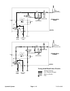
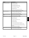
Traction Circuit
The traction (piston) pump (P1) is driven by the engine
through the pulleys and pump drive belt. The traction cir-
cuit of the hydraulic system acts essentially as a closed
loop. Taking its suction directly from the return side of the
wheel motors of the traction circuit, the traction (piston)
pump supplies oil flow to the wheel motors through the
supply side of the traction circuit.
The gear pump (P2) is attached to the traction pump and
is directly coupled to it. The gear pump provides charge
oil to replace small amounts of traction pump internal oil
leakage. Hydraulic charge oil is supplied to the traction
circuit from the gear pump, through the lift control man-
ifold (manifold port P, proportional valve PV and man-
ifold port CHG) and past the charge circuit check valve
in the return side of the traction circuit. Proportional
valve PV ensures that sufficient gear pump flow is al-
ways available for the charge oil needs of the traction cir-
cuit. Gear pump flow in excess of charge circuit needs
is available to raise/lower the coring head. After charge
and raise/lower requirements are met, excess P2 flow
is directed to the hydraulic reservoir through the hydrau-
lic oil filter.
Forward Direction
With the engine running and the traction lever in the neu-
tral position, the traction pump supplies no flow to the
wheel motors. When the traction lever is moved to the
forward position, the linkage from the lever positions the
swash plate in the traction pump so oil flows out the low-
er port of the pump. Oil flow from the pump is directed
to the wheel motors (front motor first and then rear mo-
tors) and turns them in the forward direction. Maximum
forward traction pressure is limited by a 2900 PSI (200
Bar) relief valve located in the bottom of the pump as-
sembly.
Oil flowing from the rear wheel motors returns to the top
port of the traction pump and is continuously pumped
out the bottom port as long as the traction lever is held
in the forward direction.
Reverse Direction
The traction circuit operates essentially the same in re-
verse as it does in the forward direction. However, the
flow through the circuit is reversed. When the traction le-
ver is moved to the reverse position, the linkage from the
lever positions the swash plate in the traction motor so
oil flows out the upper port of the pump. Oil flow from the
pump goes to the wheel motors (rear motors first and
then front motor) and turns them in the reverse direction.
Maximum reverse traction pressure is limited by a 2900
PSI (200 Bar) relief valve located in the top of the pump
assembly.
Oil flowing from the wheel motors returns to the bottom
port of the traction pump and is continuously pumped
out the top port as long as the traction lever is held in the
reverse direction.
Hydraulic
System