


Solenoid Valve Coil
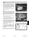
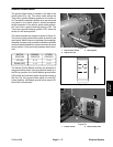
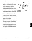
The hydraulic system on the ProCore 648 uses three (3)
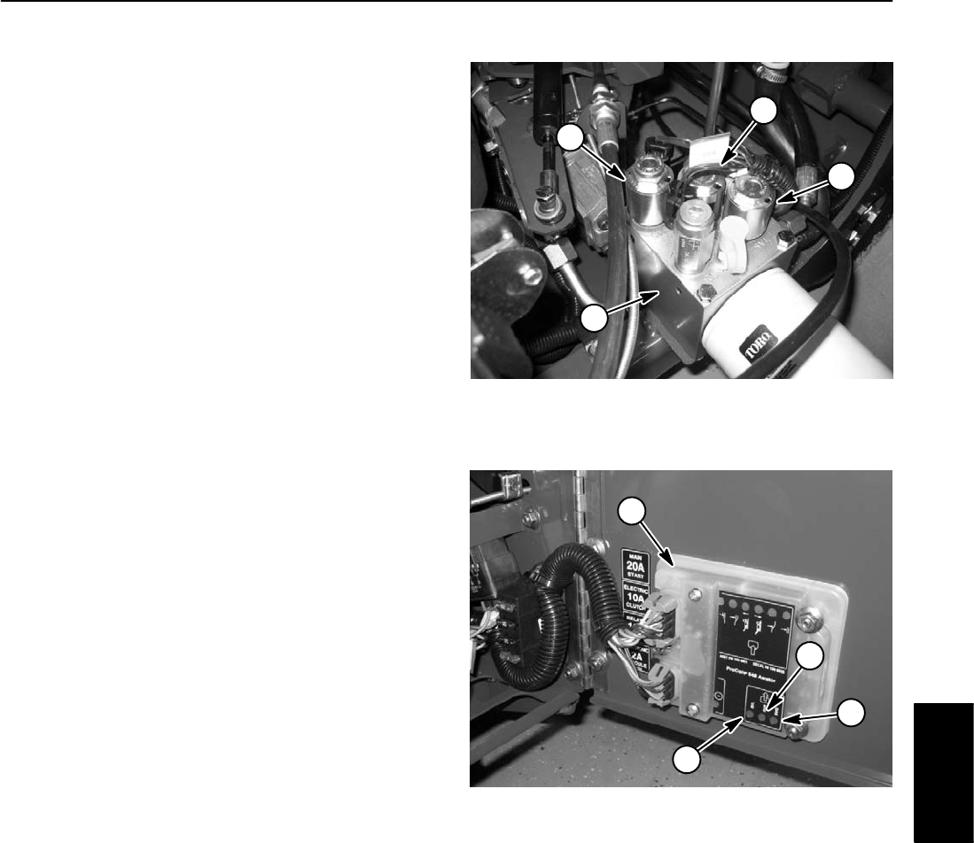
solenoid valve coils on the hydraulic lift control manifold
(Fig. 23). The aerator control module provides current to
the solenoid valve coils based on the position of several
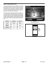
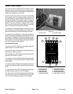
inputs. A LED on the aerator control module will be illu-
minated when the solenoid valve coils are energized
(Fig. 24).
NOTE: The solenoid does not have to be removed from
the cartridge valve for testing.
1. Make sure ignition switch is in the OFF position. Un-
plug solenoid valve electrical connector.
2. Apply 12VDC source directly to the solenoid. Listen
for solenoid to switch on.
3. Remove 12VDC source from the solenoid. Listen for
solenoid to switch off.
NOTE: Prior to taking small resistance readings with a
digital multimeter, short the test leads together. The me-
ter will display a small resistance value (usually 0.5
ohms or less). This resistance is due to the internal re-
sistance of the meter and test leads. Subtract this value
from from the measured value of the component you are
testing.
4. Measure resistance between the two coil connector
terminals. Resistance of the solenoid coil should be
approximately 8.7 ohms.
5. Reconnect electrical connector to the solenoid.
6. If solenoid coil needs replacement, see Solenoid
Valve Coil in the Service and Repairs section of this
chapter.
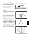
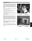
3
2
4
1
Figure 23
1. Lift control manifold
3. SVQ solenoid coil
2. SVL solenoid coil
4. SVR solenoid coil
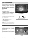
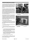
4
3
1
2
Figure 24
1. Control module
3. SVQ solenoid LED
2. SVR solenoid LED
4. SVL solenoid LED
Electrical
System
ProCore 648
Page 5 – 19
Electrical System