


Inspection
CAUTION
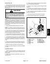
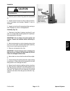
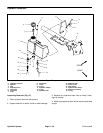
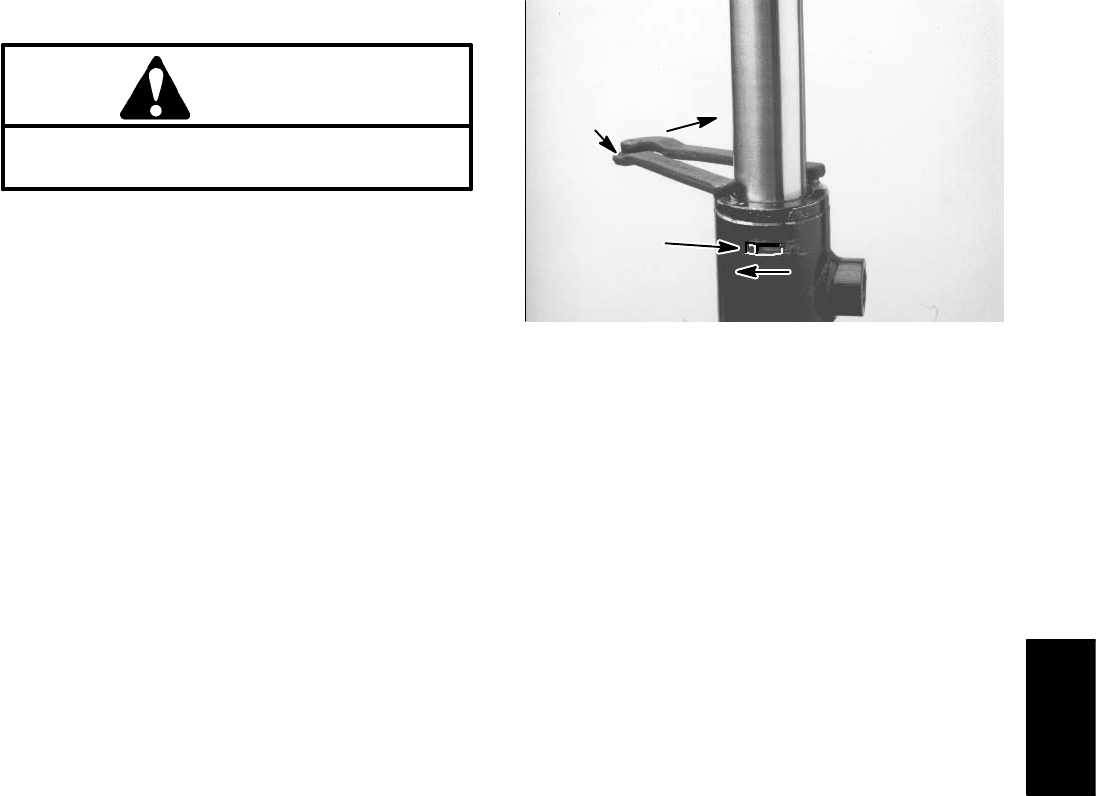
Spanner
wrench
Retaining ring
against left side of
barrel groove
after installing)
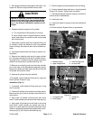
Use eye protection such as goggles when using
compressed air
1. Wash all parts in solvent. Dry parts with compressed
air.
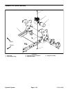
2. Inspect internal surface of tube for deep scratches,
out–of–roundness and bending. Replace if worn or
(Offset end
damaged.
Figure 46
3. Inspect rod and head for excessive pitting, scoring or
wear. Replace any worn or damaged parts.
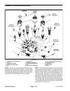
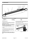
Assembly (Fig. 44)
1. Coat new o–ring (item 4), backup ring (item 5), seal
(item 7) and wiper (item 9) with hydraulic oil. Install seal-
ing components to the head.
IMPORTANT: Do not clamp vise jaws against rod
surface. Protect rod surface before mounting in
vise.
2. Mount rod securely in a vise by clamping vise on the
pivot end of the shaft. Carefully slide head assembly
onto the rod. Install retaining ring (item 1).
3. Remove rod assembly from vise.
IMPORTANT: Prevent damage when clamping the
tube into a vise; clamp on the pivot end only. Do not
close vise enough to distort tube.
4. Mount tube in a vise so that the rod end tilts up slight-
ly.
5. Coat all internal lift cylinder parts with a light coating
of hydraulic oil. Slide rod and head assembly into tube
being careful not to damage the seals.
6. Secure head in tube by installing retaining ring (item
6). Align key slot in head with the access groove in the
tube. Rotate head clockwise as far as the retaining ring
will allow. The offset end of the retaining ring will be
against the left side of the tube groove as shown in Fig-
ure 46.
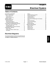
Hydraulic
System
ProCore 648 Page 4 – 53 Hydraulic System