


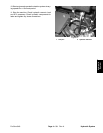
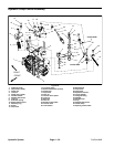
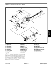

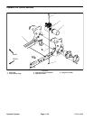

Installation (Fig. 31)
1. Install hydraulic fittings with new o–rings to the hy-
draulic pump. Orientate the fittings as noted during dis-
assembly.
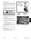
CAUTION
pump support to prevent the pump from falling
Support hydraulic pump when installing it to the
and causing personal injury.
2. Position hydraulic pump assembly to the frame
pump support. Secure pump to the pump support with
two (2) flange head screws and flange nuts.
3. Make sure the bore of the pump pulley is clean. Apply
anti–seize lubricant to the hydraulic pump shaft. Posi-
tion key to pump shaft and slide pulley onto pump shaft
with the pulley hub toward the pump. Position pulley to
the marked position on the pump shaft.
4. Apply Loctite 242 (or equivalent) to pulley set screws
and secure pulley to pump shaft with two (2) set screws.
5. Remove any caps or plugs that were placed in pump
openings, hydraulic hoses or hydraulic tubes during the
pump removal procedure. Connect hydraulic hoses and
tubes to hydraulic pump.
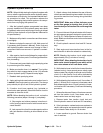
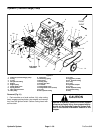
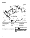
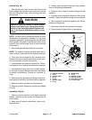
6. Install hydraulic pump controls (Fig. 32 and 33) to the
pump as follows:
A. Carefully position pump control assembly to
pump. Make sure pump lever with attached trunnion
clamp is placed over pump trunnion shaft.
B. Secure control bracket to hydraulic pump with
two (2) cap screws with flange nuts and washer head
screw.
C. Secure pump lever to pump trunnion shaft with
two (2) socket head screws.
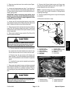
CAUTION
cause personal injury during installation. Use
The extension spring is under tension and may
caution when installing the spring to the neutral
lever.
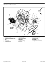
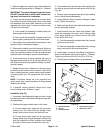
7. Place two (2) flat washers to tops of studs on pump
control assembly. Position pump shield to pump and se-
cure with two (2) lock nuts.
8. Lift idler pulley and install drive belt to the pump
pulley. Adjust drive belt tension (see Operator’s Manu-
al).
9. Install pump belt cover to machine (see Operator’s
Manual).
10.Follow Hydraulic System Start–up procedures.
11. Check traction drive for neutral and adjust if needed
(see Operator’s Manual).
12.Operate machine and check hole spacing. Adjust if
needed (see Operator’s Manual).
D. Install extension spring to the neutral lever.
Hydraulic System Page 4 – 40 ProCore 648