


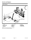
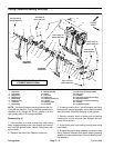
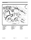
Removal (Fig. 5)
1. Park machine on a level surface, fully raise coring
head, engage parking brake, stop engine and remove
key from the ignition switch. Secure coring head with
service latch.
2. Remove rear hood (see Operator’s Manual).
3. Remove two (2) lock nuts and hardened D washers
that secure rotolink damper to coring head frame (see
Rotolink Dampers in this section).
4. If outside stomper arm (#1 or #6) is to be removed:
A. If #1 stomper arm is being removed, remove sec-
ondary coring head drive belt (see Secondary Drive
Belt Removal in this section).
B. Remove cap screw and flat washer that retain
stomper arm to coring crankshaft.
C. If #6 stomper arm is being removed, remove
spacer tube (item 12) from coring crankshaft.
D. Support stomper arm assembly to prevent it from
falling during removal. Slide stomper arm from cor-
ing crankshaft. Carefully, lower stomper arm assem-
bly from frame.
5. If inside stomper arm (#2, #3, #4 or #5) is to be re-
moved:
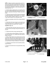
A. Remove fasteners that secure coupling plate to
coupling on stomper to be removed (Fig. 7).
B. Remove cap screw and flat washer that secures
coupling and stomper arm to coring crankshaft.
C. Slide coupling from coring crankshaft. Locate
and retrieve square key.
D. Support stomper arm assembly to prevent it from
falling during removal. Slide stomper arm from cor-
ing crankshaft. Carefully, lower stomper arm assem-
bly from frame.
6. If necessary, remove retaining ring and ball bearing
from stomper arm.
7. If necessary, remove tines and tine holders from
stomper arm (see Operator’s Manual).
8. Remove rotolink damper components as needed
(see Rotolink Dampers in this section).
Installation (Fig. 5 and 7)
1. If removed, install ball bearing into upper end of
stomper arm and secure with retaining ring.
2. Install any rotolink damper components that were re-
moved during disassembly (see Rotolink Dampers in
this section).
3. Thoroughly apply antisieze lubricant to stomper arm
shaft surface on coring crankshaft.
4. Raise stomper arm assembly up through frame.
Slide stomper arm bearing onto coring crankshaft.
5. Secure stomper arm to coring crankshaft in the re-
verse order of disassembly.
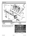
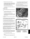
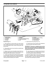
A. Torque 5/8” cap screws from 150 to 170 ft–lb (203
to 230 N–m).
B. Torque 1/2” cap screws from 70 to 80 ft–lb (95 to
108 N–m).
6. Secure rotolink damper to coring head frame with
lock nut and hardened D washer (see Rotolink Dampers
in this section).
7. After assembly, rotate coring crankshaft by hand to
make sure that no binding occurs.
8. If removed, install tine holders and tines to stomper
arm (see Operator’s Manual).
9. If removed, install secondary coring head drive belt
(see Secondary Drive Belt Installation in this section).
10.Install rear hood (see Operator’s Manual). Disen-
gage service latch before machine use.
1
2
3
4
5
6
7
8
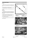
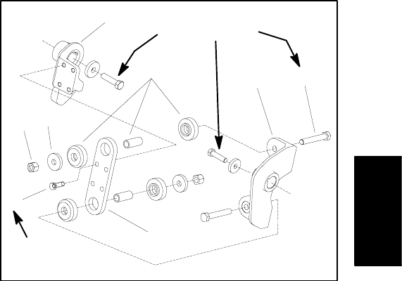
150 to 170 ft–lb
(203 to 230 N–m)
70 to 80 ft–lb
(95 to 108 N–m)
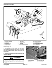
Figure 7
1. Coupling (#3 shown) 5. Coupling plate
2. Iso mount (2 used) 6. Cap screw (4 used)
3. Coupling (#2 shown) 7. Lock nut (2 used)
4. Cap screw (2 used) 8. Flat washer (2 used)
Coring Head
ProCore 648 Page 7 – 7 Coring Head