


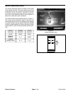
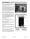
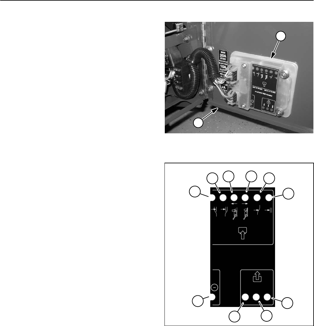
Aerator Control Module
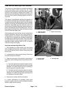
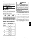
The ProCore 648 is equipped with an Aerator Control
Module to monitor and control electrical components re-
quired for safe operation. This Module is located on the
inside of the console cover (Fig. 33).
Inputs from the start (ignition), head low limit, head high
limit, transport limit #1 proximity switch, aeration #4
proximity switch and ground follow switches are moni-
tored by the Module. The condition (open or closed) of
the ”OK to lower” circuit is also monitored by the Module.
Output to the three hydraulic solenoid valves (lower
SVL, raise SVR and quick raise SVQ) are controlled
based on the inputs received by the Module.
The Aerator Control Module does not connect to an ex-
ternal computer or hand held device, can not be re–pro-
grammed and does not record intermittent fault data.
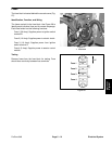
The Aerator Control Module can be used to check op-
eration of machine switches by monitoring the LED’s of
the module. If a module LED does not illuminate (e.g. the
ground follow LED does not illuminate when the ground
follow switch is in the ON position), testing of the switch
and circuit wiring would be required.
Control Module Inputs
The power input LED should be illuminated when the
ignition switch is in the ON position.
The head low input LED should be illuminated when the
head low limit switch is closed.
The head high input LED should be illuminated when the
head high limit switch is closed.
The transport #1 input LED should be illuminated when
the transport limit #1 proximity switch is closed (coring
head raised).
The aerate #4 input LED should be illuminated when the
aeration #4 proximity switch is closed (coring head low-
ered).
The ground follow ON LED should be illuminated when
the ground follow switch is in the ON position.
The ”OK to lower” input LED should be illuminated when
the ”OK to lower” circuit is closed (see OK to Lower Cir-
cuit in the Circuit Operation section of this chapter).
1
2
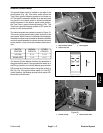
Figure 33
1. Console cover
2. Control module
1
5
2
3
4
10
9
6
7
8
SVL
SVR
SVQ
ProCore 648 Aerator
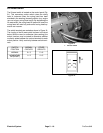
Figure 34
1. Power input LED
6. Head high input LED
2. SVL output LED
7. Transport #1 input LED
3. SVR output LED
8. Aerate #4 input LED
4. SVQ output LED
9. Ground follow ON LED
5. Head low input LED
10. “OK to lower” input LED
Electrical System
Page 5 – 24
ProCore 648