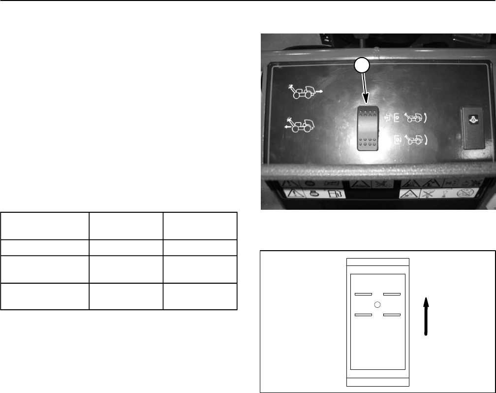
Manual Raise/Lower Switch
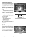
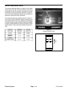
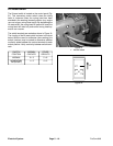
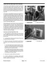
The manual raise/lower switch is located on the handle
control panel (Fig. 16). This rocker switch is one of the
components in the ”OK to lower” circuit which is one of
the aerator control module inputs. See OK to Lower Cir-
cuit in the Circuit Operation section of this chapter for
additional raise/lower switch information.
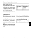
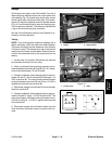
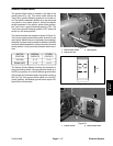
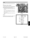
The switch terminals are marked as shown in Figure 17.
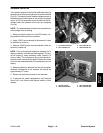
The circuitry of the raise/lower switch is shown in the
chart below. With the use of a multimeter (ohms setting),
the switch functions may be tested to determine whether
continuity exists between the various terminals for each
switch position. Verify continuity between switch termi-
nals.
1
SWITCH
POSITION
NORMAL
CIRCUITS
OTHER
CIRCUITS
RAISE NONE NONE
MIDDLE/
AERATE
2 + 3 NONE
LOWER
(MOMENTARY)
2 + 3 5 + 6
Figure 16
1. Manual raise/lower switch
6
3
5
2
UP
Figure 17
Electrical System
Page 5 – 16
ProCore 648


