


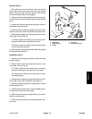
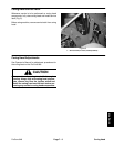
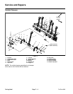
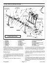
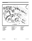

Disassembly (Fig. 4)
1. Park machine on a level surface, fully raise coring
head, engage parking brake, stop engine and remove
key from the ignition switch. Secure coring head with
service latch.
2. Remove rotolink components as needed using Fig-
ure 4 as a guide.
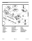
Assembly (Fig. 4)
1. If studs (item 4) were removed from damper (item
15), thread stud fully into damper.
2. If bearings were removed from damper links, press
new bearings into links.
3. Assemble all components before fully tightening any
fasteners so there is no preload on rotolink damper com-
ponents. Tighten fasteners in the following order:
A. Secure damper links (item 9) to stomper arm
(item 11) and damper (item 15). Torque lock nuts
(item 7) from 150 to 170 ft–lb (203 to 230 N–m).
B. Tighten two (2) flange nuts (item 12) that secure
damper links.
C. Tighten two (2) lock nuts (item 1) that secure
damper to frame.
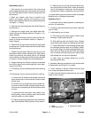
4. After assembly, rotate coring crankshaft by hand to
make sure that no binding occurs.
NOTE: If using longer, solid tines, damper top spacer
(item 17) might not be installed (see Operator’s Manu-
al).
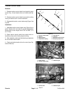
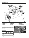
5. If damper standoff (item 16) and top spacer (item 16)
are both installed on rotolink damper, rubber bumpers
(item 16) should contact bumper plates (item 5). If only
damper standoff (item 16) is used, rubber bumpers
should contact frame (bumper plates moved forward).
6. Remove service latch from coring head before using
machine.
ProCore 648 Page 7 – 5 Coring Head
Coring Head